A transverter for 10.368 MHz
In recent years the microwave bands above 2304 MHz have shown rapid growth. More parts have become available from surplus, and as a result more amateurs have been building equipment for all bands above 900 MHz.
I'd like to promote activity on 10 GHz by showing how I built an SSB/CW transverter for less than $200. The project didn't require much time or test equipment. A block diagram of the transverter is shown in fig. 1. The completed unit is shown in photo A.
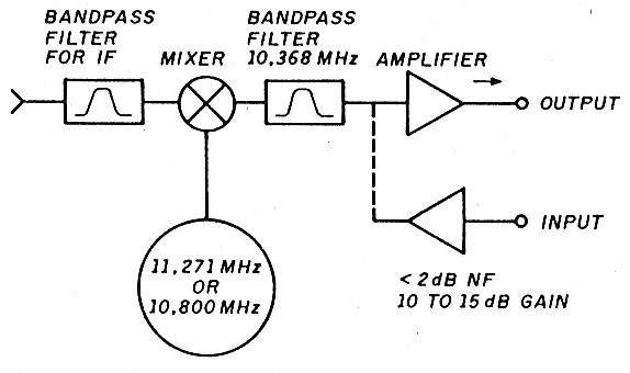
Fig. 1 - Block diagram of the transverter.
Local Oscillator
You may wonder if an inexpensive local oscillator will provide good service. I found units from Frequency West and California Microwave were about the best (see photo B). Both were made in the 1980s and depending on the unit have outputs between 5 dBm and 20 dBm. All are stable enough for SSB, CW, or FM.
Some of the oscillators have inputs for FM use and require -19 volts at 400 mA for operation. Most of the output ports are WR75 waveguide, but some use SMA output connectors. The units I acquired had WR75 waveguide ports, and after removing the assembly, I found that there were holes to mount an SMA connector under the waveguide. The units are dielectric resonating oscillators (DRO) locked to a crystal reference. The drift at 11,200.000 MHz is measured at less than 500 Hz after a 30-minute warm-up.
The units will have to be retuned for the amateur band. To do so, lock the oscillator to the new crystal and adjust the comb-line filter for maximum output. Loosen the lock nuts holding the set;rews in place to gain access to the filar. A power meter is a must here. A spectrum analyzer will let you ascertain that the oscillator is locked.
Intermediate Frequency
Locating a new crystal isn't difficult. You can obtain one from ICM, Bliley, and others for about $17. For an IF of 432 MHz, the LO should be set to 10,800.0 MHz; for a 903 MHz IF it should be 11,271.0 MHz. Some of the oscillators divide by 108 MHz and some by 118 MHz. To find out which type you have, divide the output frequency (marked on the unit) by the crystal frequency.
Most of the units can't be tuned low enough to use an IF of 2 meters. Consequently, I used an IF of 432 or 903 MHz. This means you must use high injection. By choosing an IF of 903 MHz, I was able to build a transverter for a 10.3 GHz project (see photo C) and another for a 903 MHz project. The 903 MHz IF assures the fixer images will be well outside the passband of most filters. This means that the output filter doesn't have to be as sharp as it does for an 144 MHz IF. For the output filter I used part of the x6 assembly from another unit less the SRD device. Again, because 11,271.0 MHz is farther away from 10,368.0 MHz, the output filter doesn't have to be sharp.
Mixer
Finding a mixer for 10.3 GHz can be a problem, so I tried to develop my own.
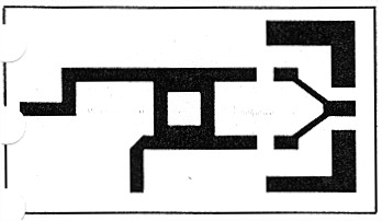
Fig. 2 - Board layout of the mixer.
Fig. 2 shows my PC board layout and photo D shows the parts placement. The board was laid out on ROGER DORID 5787. All capacitors were 10 pF and type ATC 100. The diodes were Hewlett-Packard 5082-2200. I chose these because they are designed for stripline and microstrip mixers and detectors, have a test frequency of 9 GHz, and have a burn-out rating of 125 mW of CW RF power.
After etching the board, I mounted it on a block of brass (copper could be used as well) by heating the block on my kitchen stove. When the block was hot enough to melt solder, I coated it with solder and dropped on the mixer board.
I used a heavy heat sink to keep the board from "bowing up" as it cooled. You'll need to let the mixer cool for about 30 minutes before handling it. After cooling is complete, mount the components and SMA connectors. Building your own mixer can save you money, as a mixer for this frequency can cost about $400. I tried the HMXR-5001 mixer from Hewlett-Packard. It worked well, but mixers like that don't show up at swap meets.
The input power to the mixer's IF port was 0 dBm (1 mW) and the LO power was 10 dBm (10 mW). The insertion loss was about -9 dB, with LO-to-RF isolation about of - 20 dB. I laid out the mixer with a lowpass filter at the IF port. I added a bandpass filter to this to suppress any spurious oscillations generated by my 903 MHz transverter.
Power Amplifiers
Power amplifiers for this band are hard to come by. One source for parts is Surplus Sales of Nebraska. They had a 7 to 11 GHz amplifier with 34 dB gain and a noise figure of 4.5 dB for $125. The noise figure may be higher than you wish, but at this price you can still use it for a power amplifier or driver. I found some preamps with layouts by WB5LUA in Microwave Update 88. The GAsFets used for the amplifiers are the Avantek ATF 13135 purchased from Pennstock for $33 each. Under test the amplifiers measure about 8 dB gain and have a noise figure of 1.3 dB for the single unit, with about 17 dB gain and a 1.5 dB noise figure for the double unit. The 1 dB compression point may be about 10 to 20 mW. Fig. 3 shows the amplifier schematic; a one-to-one PC board layout appears in fig. 4.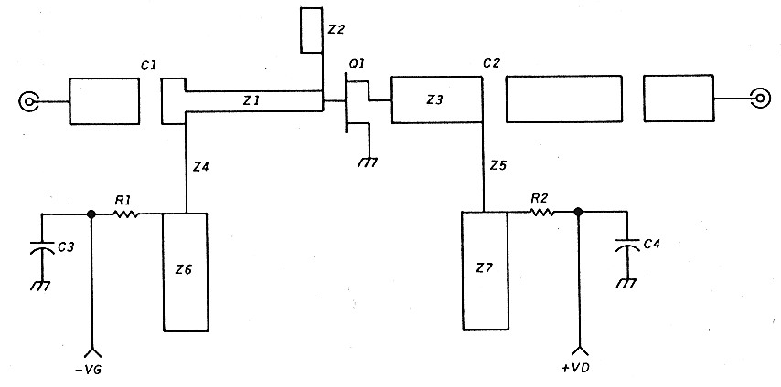
Fig. 3 - Schematic of the 10.3 GHz preamplifier.
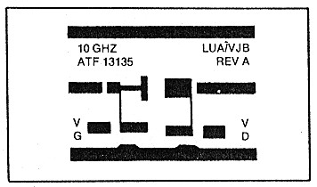
Fig. 4 - Preamplifier 1:1 board layout.
The traveling-wave tube (TWT) is another power source you may wish to explore. Outputs of 50 to 100 watts are now being used on the band for EME. TWTshave gains on the order of 30 to 40 dB, so you need only a very small amount of power to drive most of them to full output. For a 10 watt TWT amplifier, 100 microwatts may be all that is required for full output.
The 10.3 GHz part of the transverter was mounted above an aluminum chassis. The 903 MHz transverter, built to drive the 10.3 GHz transverter, was mounted below. The output was about 5 mW, with about 3 dB cable loss and 0.5 dB loss in the 903 MHz bandpass filter. I built another transverter with an output of 5 watts just for 903 MHz.
Tune-up is easy because you test all subassemblies before putting everything together. The IF bandpass filter need be tested only once; the oscillator is then locked onto the new frequency. You'll need an RF generator, HP432 power meter, and a spectrum analyzer for all of the alignments. A spectrum analyzer aids in tuning the filters, locking the oscillator, and looking for spurious responses from the amplifier.
Power Supply
Power for this project is 12 volts at 0.2 amps and - 20 volts at 0.4 amps. This meant I needed to build a power supply (see photo E). Al Ward, WB5LUA, and Greg Raven, KF5N, built a +12 to -20 volt DC-DC converter power supply using inexpensive parts. Fig. 5 shows the power-supply schematic. You can find most of the parts at Radio Shack or other parts outlets. For L1, use a T-106-26 iron-powder core from Amidon Associates with 37 turns of #18-or 20-gauge wire. The 9.1 k ohm resistor that I used may not be easy to find, but you can parallel a 10 k and 100 k resistor. I didn't use a PC board here, as the overall layout isn't critical.
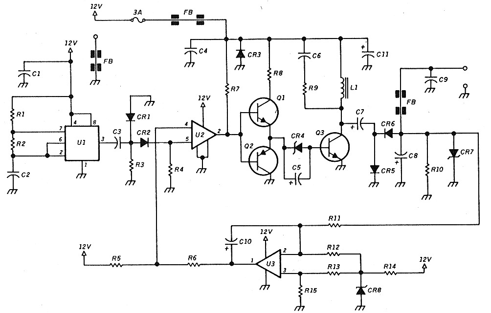
Fig. 5 - Schematic of the +12 to -20 volt power supply.
24.192 MHz Transverter
Though I concentrated on building a 10.3 GHz transverter. It's only a matter of add ing another mixer and LO for 13,824 MHz to go from 10.368 to 24.192 MHz. Fig. E shows the basic idea. This project is stil on the drawing board, but could work like this:
- Start with any CW source that wil give you 2304 MHz output.
- Remove a x6 stage from an 11 GH2 brick and retune it for maximum output a 13.824 GHz (2304 x 6 = 13,824).
- Make or buy a mixer for 13 GHz.
The 11 to 12 GHz bricks will be hard tc tune. Use them as is, so only the outpu portion is utilized. The cost of just the out put multiplier, in working order, was $8. haven't yet built the 24 GHz unit.
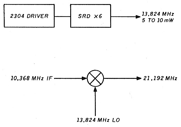
Fig. 6 - 24 GHz block diagram.
Conclusion
With improved technology and increase( parts availability, 10.3 GHz and beyon( are within the reach of all amateurs. Find ing others in your area with the same in terest may be a bigger problem thar building the equipment. But don't give up Some day soon we may see a DXCC or 10.3 or 24 GHz.
Parts List
Power Supply
| R1 | 4.7 k |
| R2, 3, 6, 7, 12, 13, 14, 15 | 1 k |
| R4 | 2 k |
| R5 | 3 k |
| R8 | 100 ohm |
| R9 | 200 ohm |
| R10 | 10 k |
| R11 | 9.1 k |
| C1, 3, 4 | 0.05 uF |
| C2, 6, 9 | 0.01 uF |
| C5, 10 | 1 uF |
| C7 | 100 uF/25 V DC |
| C8 | 220 uF/25 V DC |
| C11 | 2200 uF/25 V DC |
| CR1, 2 | 1N914 |
| CR3, 5, 6 | 1N4001 |
| CR4 | 5.1 volts |
| CR7 | 26 volts |
| CR8 | 5.1 volts |
| L1 | 100 uH |
| FB | Ferrite bead |
| U1 | 555 |
| U2 | LM339 |
| U3 | 714 |
| Q1 | PN 2222 |
| Q2 | PN2907 |
| Q3 | TIP 3055 |
10.3 GHz Preamplifier
| C1, 2 | 2.7 pF 0.05 inch square-chip capacitors |
| C3, 4 | 1000 pF chip capacitors |
| R1,R2 | 51 ohm chip resistors |
| Z1-Z7 | Etched microstrip circuitry |
| Q1 | ATF 13135 |
WA3IAC, Chuck Steer