The practical aspects of VFO design
Plus How to Build One
How many times have you struggled to obtain acceptable frequency stability and the desired output power from a homemade VFO? The challenge is a difficult one, especially when output power greater than a milliwatt or so causes transistors to generate heat. This heat encourages long-term frequency drift.
There are a number of things we cando to ensure VFO stability. This article treats the design methods I use to obtain VFO performance which parallels, and at times exceeds, that of the local oscillators in commercial amateur gear. We will also examine the circuit for a practical, stable VFO that you can build and get working in a couple of hours. The VFO is suitable for transmitters, receivers, and a host of other equipment.
Choice of VFO Components
Try to avoid using silver-mica capacitors in your VFO. These parts were once considered excellent choices with respect to stability, but better capacitors are available today. Silver micas are not uniform in their temperature-stability characteristics. Some exhibit positive drift, while others have a negative-drift trait. Painstaking experimenting can produce a set of silver-mica capacitors that are temperature-stable, but I prefer to avoid this process for grading them. Rather, I use NPO ceramic capacitors in the frequency-determining part of the VFO circuit. A fine second choice is the polystyrene capacitor, which is cheap and has a slight negative drift characteristic. This negative coefficient complements the positive coefficient that is common to most powdered-iron cores, such as toroids and slug-tuned coils. The result is often superb stability. A wide assortment of NPO capacitor values are listed in the Mouser Electronics catalog (call 800-992-9943 for a free catalog) and their individual cost is modest.
An ideal VFO would have no magnetic core in the main VFO coil. A rigid air-wound inductor or one wound on a ribbed ceramic form would yield the best O and the least drift. This approach is seldom practical today, owing to the need and desire to build miniature equipment. Powdered-iron cores change permeability as the ambient temperature in the VFO compartment changes. There is also a minor change in coil temperature that is caused by circulating RF current. This temperature variation causes what we know as "long-term drift." The VFO frequency may not settle down for 30 minutes to one hour. Some poorly designed VFOs never stabilize.
If I use a magnetic core for my VFO inductor, I employ No. 6 material, such as the Amidon or Micrometals Corp. yellow-coded toroids. This mixture seems to have the best overall stability for HF oscillators. These cores are made from Carbonyl SF material. Likewise for the core material in slug-tuned forms. The completed coil should be doped twice with General Cement polystyrene Q Dope.' This keeps the coil turns from moving and changing the value of distributed capacitance. Such changes would otherwise occur from vibration and changes in heat.
It is important also to select the right transistor for the oscillator. I personally don't care for bipolar transistors. They exhibit greater changes of Internal resistance and capacitance (with heat) than are found when using JFETs or MOSFETs. The 2N4416 is my favorite device for VFOs because it has a high pinch-off characteristic. This permits the device to produce greater output power than is available from the somewhat generic MPF102 family of FETs. I also have obtained good performance from dual-gate MOSFETs such as the RCA 40673 and TI 3N211 and 3N212 devices. I often tie gates 1 and 2 together and use the transistor as a single-gate device. This eliminates the need to bias gate No. 2.
The VFO tuning capacitor needs to be of good mechanical design. Double-bearing capacitors that turn freely are best. Try to avoid using capacitors that have aluminum vanes. These are rather temperature sensitive, and this causes drift. Plated brass or iron vanes are better. A variable capacitor that is tight or "lumpy" when adjusted will cause backlash and frequency jumps.
Half-watt carbon film or carbon composition resistors may offer greater stability than 1/4 watt units, owing to the difference in physical size. The larger resistors can take more heat before they change value.
VVC (varactor) tuning diodes complicate the stability factor. This Is a result of changes In diode junction capacitance with temperature. As the bias is changed on these diodes there will be a change in junction temperature, and this causes drift. Try to use mechanical tuning capacitors when you can.
More Aids for Stability
I have learned that using two or more capacitors in parallel to obtain a specific capacitance value is helpful in obtaining VFO stability. Specifically, I might use two 50 pF NPO capacitors In parallel to secure 100 pF. This provides greater internal surface area for the capacitor, which minimizes heating from RF currents. The same trick has proven useful for the feedback capacitors in a Colpitts oscillator.
Don't use double-sided PC boards for your VFOs. The etched-side conductors form low-Q capacitors in combination with the ground-plane side of the PC board, and these unwanted capacitors are very unstable. I prefer to use single-sided G-10 glass epoxy board material for my VFOs. I do not use phenolic base board material, even though it costs less than the quality board stock.
Separating the oscillator portion of the VFO from the buffer and amplifier stages Is important, too. The heat tends to build up in the VFO shield enclosure even when small transistors are used. It is wise to put a shield divider (made from PC-board stock) between the oscillator and the stages that follow. The cover for the VFO box can then be vented above the buffer and amplifier stages to let the heat escape before it reaches the oscillator circuitry. This shield acts as a heat baffle. I learned this kink from Zac Lau of the ARRL staff.
It is wise to use the lowest operating voltage practicable for the oscillator. The power the Vcc or Vdd, the less internal heat for the transistor. I prefer an operating voltage between 6 and 8 for the solid-state oscillator. I have had good results when using 9 volts also. In any event, this voltage should be regulated by means of a Zener diode or small three-terminal regulator.
The DC leads that enter the VFO box should be filtered by way of an RF choke and 0.001 µF feedthrough capacitor. This measure keeps unwanted RF energy from entering the VFO circuit. Stray energy of this variety can cause VFO instability, especially when the VFO is used in a transmitter.
Short- and Long-Term Drift
We encounter two types of frequency drift when operating a VFO. Short-term drift generally occurs during the first five minutes of operation. This drift is caused by internal heating of the transistors and frequency-determining components. Frequency change is usually the greatest during the short-term cycle.
Long-term drift should end within an hour of operation, and it should not exceed 100 Hz in a well-designed VFO. If you monitor the frequency changes with a frequency counter, you will note that they may occur "uphill" or "downhill," depending upon the temperature characteristics of the VFO components. It is not uncommon to observe the VFO frequency drift 100 Hz lower in frequency and then creep back to within a few Hz of thestarting frequency. Once stabilization is reached, the frequency may ramp up and down five or ten Hz until the VFO is turned off and started again. A frequency counter is a valuable tool for VFO builders.
A Practical Colpitts VFO
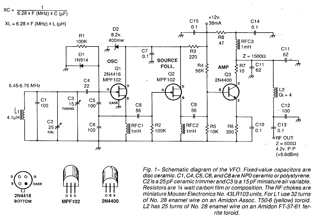
The circuit for my pet VFO is shown in fig. 1. There is no razzle-dazzle associated with this VFO. It is stable and easy to get working. The PC board artwork for this project is found in fig. 2. Plated and drilled PC boards are available at a nominal cost. The board is small enough to permit reasonable miniaturization of your project.
The VFO operating frequency specified in fig. 1 was chosen for a 75 meter superhet receiver I built. It has an IF of 2.75 MHz. This circuit can be modified easily for other tuning ranges by merely determining the capacitive and inductive reactances of the critical components (tuned circuits) and scaling them for a different frequency. The circuit is suitable for use from 1.8 through 10 MHz with no other changes.
Output power from this VFO is 4.6 mW or +6.6 dBm. The output network is designed to interface with 500 ohms. This makes it suitable for use with most bipolar RF amplifiers and IC types of mixers. C11, C12, and L2 need to be modified if you wish to connect the VFO to a 50 ohm load, such as a diode doubly balanced mixer.
D1 is used to stabilize the Q1 bias. Q2 is a source follower buffer stage that isolates the oscillator from amplifier Q3. The high-input impedance (set by R2) minimizes loading at the output of the oscillator. The Q2 drain voltage is also regulated by means of D2. This helps to eliminate oscillator load variations with changes in operating voltage.
Q3 functions as a class A amplifier. R7 has been Included to prevent VHF parasitic oscillation, which often plagues transistors with an fT In the VHF or UHF range. C11, C12, and L2 form a pi-network matching circuit that has a low-passcharacteristic. This network helps to reduce harmonic output currents.
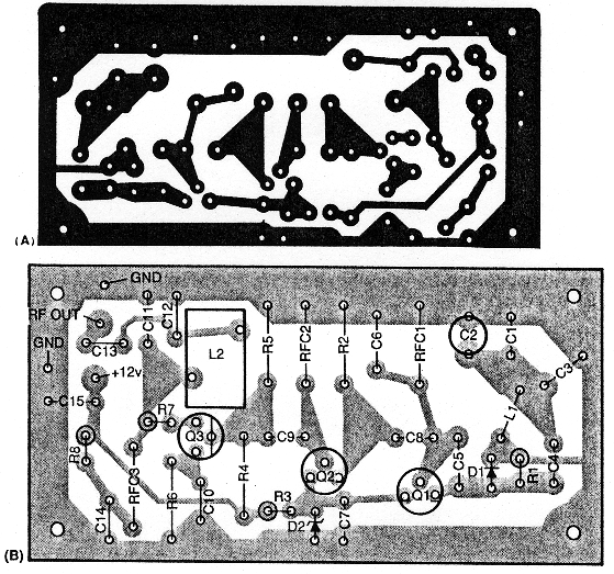
Fig. 2 - Scale etching template (A) for the VFO, as shown from the etched side of the board. An X-ray (not to scale) of the component side of the VFO board is shown at (B).
Construction Notes
This VFO may be enclosed in a homemade box that is constructed from pieces of double-sided PC board while using a 40 watt soldering iron to join the sections at the box corners. The PC board is then soldered to the box walls on four sides. Locate the PC board at least Va Inch above the bottom edges of the box. This will minimize unwanted capacitance-change effects between the PC-board conductors and the chassis on which the box is mounted. Such changes occur if the chassis is flexed under stress. Allow additional space for tuning capacitor C3 at the Q1 end of the VFO enclosure.
L1 is mounted near C3, above the VFO board, on a piece of plastic or wooden rod that Is attached at each end to the box walls. The ends of the rod are drilled and tapped for 4-40 screws. Pass the rod through the center of the L1 toroid and glue the toroid to the rod with a drop of epoxy cement.
A U-shaped aluminum cover is used for the VFO enclosure. Attach It to the box by means of four No. 4 or No. 6 sheet-metal screws. Drill several ventilation holes in the cover at the Q2, Q3 end of the box. Finally, solder a piece of PC board between the box walls to provide a heat baffle between Q1 and the two other transistors. This baffle should extend from the PC board to the box lid. A nibbling tool can be used to notch the bottom edge of the baffle where components would otherwise prevent a snug fit to the PC board.
VFO Adjustment and Performance
My tests were performed at 6.7 MHz with a room temperature of +70 degrees F. Short-term drift amounted to 2 Hz during the first 5 minutes of operation. Longterm drift was checked next. The frequency drifted 75 Hz lower, then back to within 10 Hz of the starting frequency before stabilization occurred. This took 35 minutes. These tests were made with the VFO terminated at C13 with a 560 ohm resistor. Oscillator isolation was checked by shunting a 10 ohm resistor across the 560 ohm one. This caused a 4 Hz frequency shift, thereby indicating that Q2 and Q3 were providing good load isolation.
Trimmer C2 is adjusted to provide the desired tuning range for C3. The value of C3 determines the frequency spread of the VFO. The tuning range may be reduced by using an NPO fixed-value capacitor in series with C3. Some experimentation will be required to determine the proper value for the series capacitor.
W1FB