70 cm EME-PA with 1k+ Output 2
2.2 Anode circuit details and socket assembly.
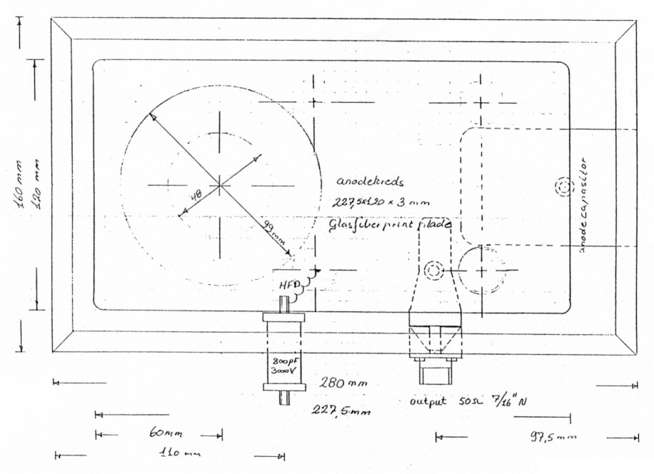
Fig 5: Anode line top.
Figure 5 shows a top view of the anode line with the output and tune flappers. Figure 6 shows a side view of the anode cabinet with anode line, chimney, tuning actuator rods and the construction of the socket assembly. The high voltage choke is wound from 0.8 mm copper wire on a 6 mm diameter form with a length of 170 mm. One end is fastened to the stripline and the other to a 5 kV feedthrough condensator of 800 pF.The anode cavity is screwed with M3 brass screws about 20 mm apart. The air input hole for the blower is covered by copper gaze to insure a RF-tight enclosure. The blower should be a medium one with a minimum air flow of 1.5 m3 per minute with 15 mm back pressure (1.5 mbar). A EBM-G2E 108-AA is suitable.
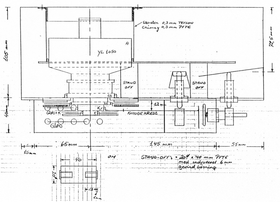
Fig 6: PA side view.
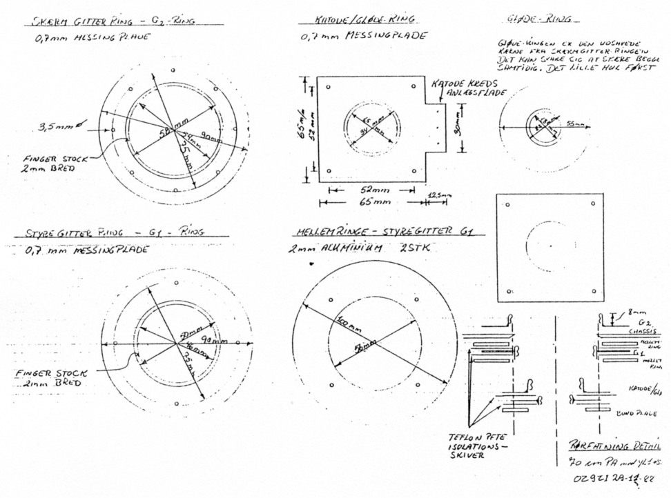
Fig 7: Parts for socket
The individual parts of the socket assembly are shown in Figure 7. The screen grid is on ground potential. The high RF-current in the anode circuit flows over the screen grid also, because it's the ground terminal for the output circuit. Instead of loosing RF-power in a dielectric, i.e. in a screen grid capacitor, the DC-grounded screen grid improves efficiency by avoiding any dielectric losses and assures stabiltity because of the low inductance path in the screen circuit.
The insulating sheets for grid 1 and the cathode capacitor are made from 0.3 mm PTFE (Teflon)-Sheets. That gives about 470 pF for Cg2 and 100 pF for Ck. Careful assembly is necessary, because Grid 1 has a potential of -750 Volt to Ground.
2.3 Cathode Circuit
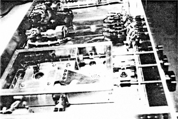
Fig 8: Picture of cathode circuit.
The cathode circuit is a low impedance (40 Ohms) half wavelength stripline with a somewhat strange shape, which has been chosen because of mechanical constraints (Figure 8). The mechanical arrangement can be seen in Figures 9, 10. The stripline is mounted in a distance of 12 mm to the main construction plate. Tuning is done by a tuning screw with a small plate at the end of the stripline. Coupling is performed by a 11x47 mm brass plate, which is soldered to the input connector.
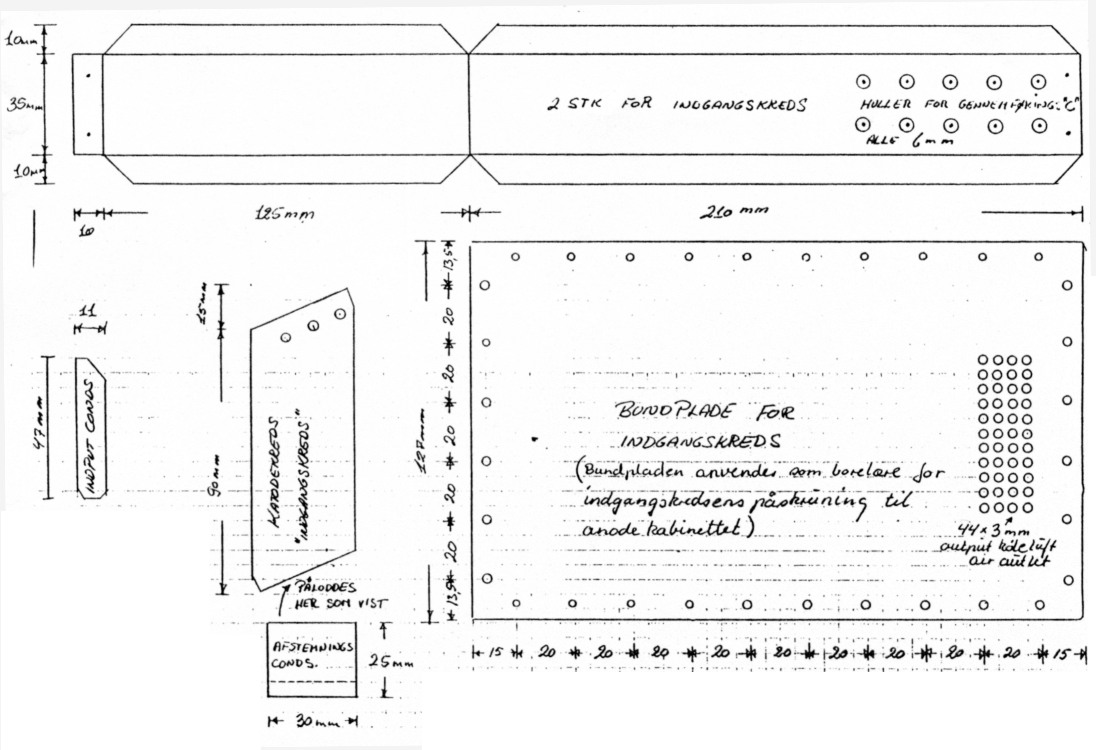
Fig 9: Parts for cathode circuit.
Further details in figure 10 show the 2.2 µH choke for Grid 1 and the two quarter wavelength (170 mm) chokes for the heater. They are made from 1.5 mm copper wire, each 170 mm long, wound on a 10 mm diameter form.

Fig 10: Cathode circuit.
2.4. Power Supply
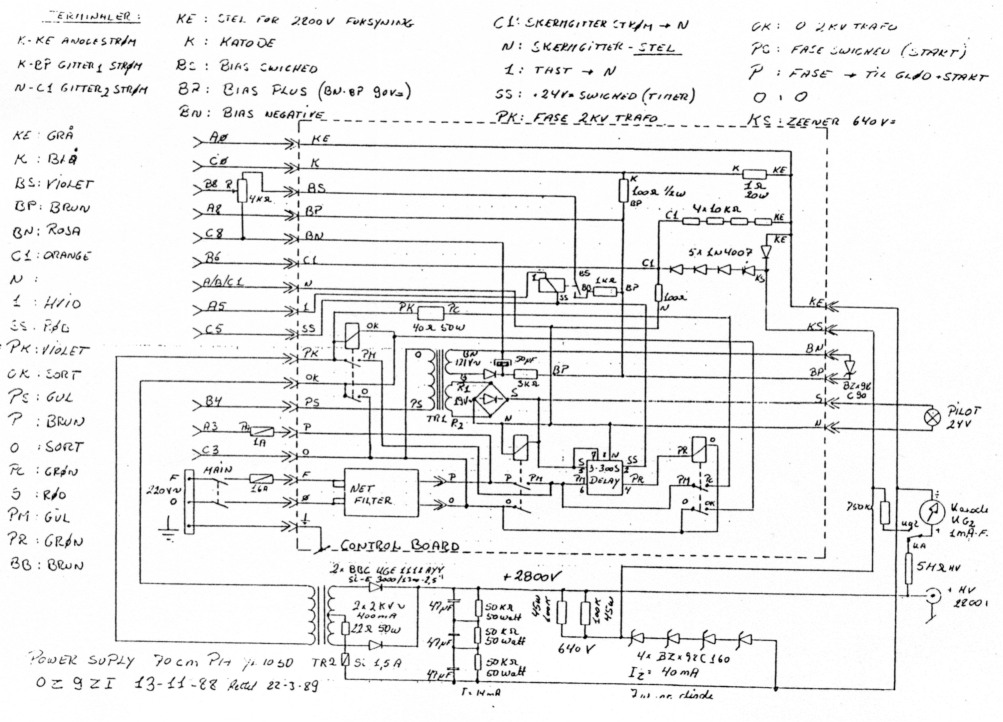
Fig 11: Power supply.
The basic idee is to have the screen at ground potential - 30 years ago it has been used in the Collins 30S1 PA -. The power supply circuit can be seen in Figure 11. The high voltage is generated by a full-wave center-tap rectifier circuit from the high voltage transformer, which has a rating of 2x2000 Volts with 400mA. The resulting DC-Voltage of 2800 Volts is divided by string of ZenerDiodes (7 W dissipation) into -640 Volts for the cathode and 2200 Volts for the anode. The filter capacitor for the high voltage is made from three Siemens MKV 47 µF condensators. Each capacitor, which is rated for 640 Volts AC and for 1000 Volts DC, is shunted by a 50 kOhms, 50 Watt bleeding resistor. Together with the current through the zener diodes a bleeding power of 170 Watt is drawn during standby.
Because of the small transformer, the anode voltage drops from 2800 to 2200 Volts with an anode current of 800 mA. For CW a bigger Transfomer with a rating of 800 mA should be chosen. In case of flash over in the anode circuit the string of 5 diodes from line KE to KS protects the zener diodes. The very same diodes provide a path for negative screen grid current also. The screen supply is bleeded by the string of four 10 kOhms resistors and for AC by two 16 uF condensators.
The supply voltage for Grid 1 is referenced to the cathode voltage of -640 V. A half wave rectifier and a stabilisation circuit generate -90 V. During standby this voltage cuts off the tube. On transmit a relay switches in a potentiometer, which can be adjusted to the necessary value for the idling current of 200 mA.
The high voltage power transformer gets its primary voltage throug a delay relay after 180 seconds. Then a soft start is caused by a series resistor of 40 Ohms/50 Watts in the primary. This surge protection is switched off after some seconds.
The transformer for the heaters is located directly in the PA-cabinet, to reduce ohmic losses with the heater current of 20 amps. The heater voltage, measured directly at the socket, should have a value of 3.8 Volts +- 5 percent.
Metering is provided for Ia (0...1.5 A); Ig2 (-10...+40 mA) and Ig1 (0...10 mA). Additional metering could be provided for anode voltage and output power.
2.5 Tune up and operation
Before applying any power to the PA, the power supply should be checked for proper operation and voltages. Then the PA can be connected. First the heater voltage should be controlled. It must have a value between 3.65 and 3.95 V, the proper value is 3.8 V. After connecting a dummy load of at least 1000 W power handling ability, a power meter at the output and an optional SWRmeter at the input as well as a transmitter with variable output power (5 - 50 W), the idling current is set to 200 mA with no RF-power but transmitter and PA keyed. Then an input RF-power of5 W is applied. First the ouput circuit is tuned to maximum with the tune flapper. Leave the load flapper as it is, because with low power there is no significant influence of the load flapper. Then the input circuit can be optimized for lowest VSWR. The input coupling flapper has to be moved or even shortened or lengthened with retuning of the tuningscrew up to a VSWR lower than 1.2.
This adjustment does not change very much for higher input power. In a second step the input power should be increased to 15 W. At this level the output controls - load and tune - can be optimized for highest possible power. A good indicator of having the right loading, i.e. the right value of anode load impedance, is the screen current. tries getting positive the right value is very near. It should have a positive value of at least 10 mA but never have a value above 40 mA, because at this value the maximum screen dissipation will be reached.
With 25 W drive level the following measurements are typical:
| Drive Power | 25 W |
| Output Power | 1000 W |
| DC-Power | 1785 W |
| Efficiency | 56 % |
| Gain | 16 dB |
| Anode Voltage | 2200 V |
| Anode Current | 810 mA |
| Screen Current | 15 mA |
| Control Grid Current | 2 mA |
At this power level no signs of thermal drift have been observed. The tube loafs along with just half of its power capability. For different power levels retuning is necessary. Loading is adjusted for the right screen grid current ( 15 - 30 mA ), whereas tuning always should be adjusted to maximum power. That occurs together with a peak in control grid current. Maximum allowable control grid current is about 50 mA.
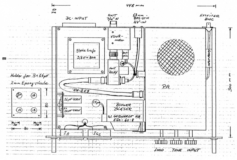
Fig 12: Construction.
Part 1 - Part 2.
OZ9ZI, Steen Gruby.