SSB-Millimeterwellen-Baugruppen 24 und 47 GHz
1. 24 GHz Mixer with LO-Doubler
In 1988 the circuits for a 24 GHz mixer and a 11.5 to 23 GHz doubler have been introduced on the VHF/ UHF convention in Munich. These circuits have been integrated onto one PCB including the power regulation circuits. The mixer can be used with an ordinary 11.5 GHz LO and is applicable as an up - converter for transmit and as a down-converter for receive. By completion with a relais, filter and amplifiers a complete transvener module for 24 GHz can be built.
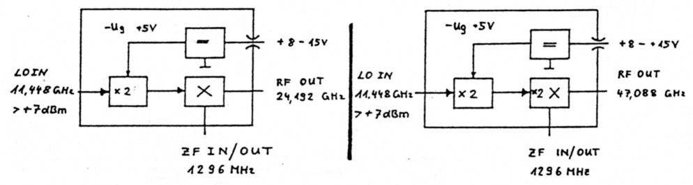
Figure 1: 24 GHz Mixer
The LO-signal with a power level of 5 mW at 11.5 GHZ is doubled with the MGF-1303 LO-doubler. A quarter wave line at the output cares for supression of the 11.5 LO-signal and determines the doubling efficiency of the GaAs-FET. Its length is 4.65 mm for 11.44 GHz LO-frequency (i.e. IF-frequency of 1296 MHz) and 4.48 mm for a 11.88 GHz LO-frequency (i.e. IF-frequency of 432 MHz). The GaAs-Fet doubler can be used with different bias voltages. 'Good' voltages are Vgs = 0 V or Vgs = Vp - 1V. With trimpot R2 the appropriate voltage can be choosen for maximum efficiency. The ouput power on 24 GHZ has a typical value of 5 mW. This power drives a classical rat-race mixer, which has proven properties concerning the LO-rejection and conversion loss. Important is the selection of usable mixer diodes. Experiments with BAT-14 had been a complete failure. An immidiate success was possible with beam-lead diodes like HP-HSCH5312/5310 or Siemens BAT14-110S. These diodes have a capacitance of 0.15 pF only. The performance feature measured are a conversion loss of 7 dB and a LO-rejection of 20 dB. Maximum output power is about 0 dBm (1 mW).
2. Construction Details
The mechanical dimensions of the PCB (DUROID RT5870 with 0.25 mm thickness) are 40 x 27 mm.The through-'holes' in the PCB are marked with black stripes in the component layout above (Figure 3). At these locations small slashes are cut through the PCB with a sharp knife and stripes of 0.1 mm copper foil soldered on both sides makes a good ground connection. The radial stub in the mixer should be grounded by a 0.1 mm copper wire.
Especially the gain of the RF-stage is dependent on a good ground connection. After inserting all components and check of the power supply the GaAs-Fets can be soldered in. The coupling caps are 0.5 pF SMD-Chips with a size of 0805. On 24 GHz one can construct small caps from 0.12 mm RTDuroid. After cleaning the beam-lead diodes are glued into the PCB with silver glue. The matching elements are not printed to allow use of various types of GaAs-Fets. The cut leads of these GaAs-Feu are used for matching instead. The position of the open stubs is indicated in Figure 3. Tuning is done by trial and error.
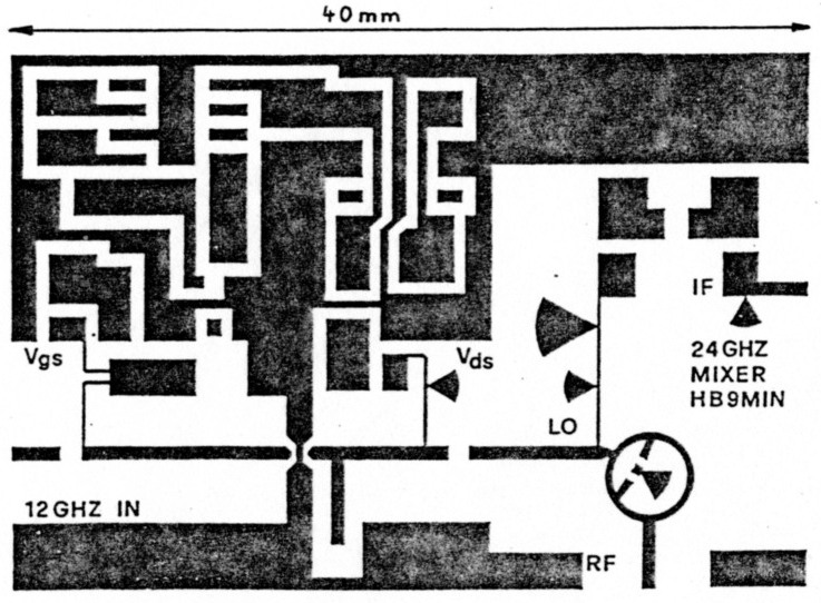
Figure 2: PCB 24 GHZ Mixer
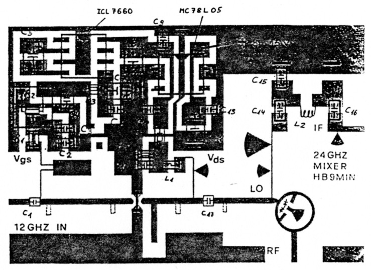
Figure 3: Component Layout 24 GHZ Mixer
3. Tuning
- Apply voltage and adjust Vgs for an Id of 5 mA
- Apply LO with an power of -10 dBm. Adjust input circuit of doubler for maximum Id.
- Connect power meter to 24 GHz output. Include Filter. Apply + 10 dBm of IF-power. Adjust matching on doubler output for maximum output on 24 GHz
- Reduce LO-power to 5 dBm. Adjust Vgs for maximum output. Adjust input and output match again.
- Adjust IF-match for lowest return loss.
4. Components
| C1 | 0,5pf SMD Keramikkond. 0805 |
| C2, C4, C6, C9, C10, C11, C13, C16 | SMD Keramikkond. Grösse 0805 |
| C5, C8, C12 | SMD Tantal Kondensatoren 2,8 x 3,4mm. |
| C14, C15 | optimieren auf gutes ZF-VSWR |
| L1 | TDK SMD Ferritperle oder 10 wird Grösse 0805 |
| R1, R3, R5 | SMD Widerstände Grösse 0805 |
| R1 | Potmeter SMD 8 EVM-7YS Panasonic |
| IC | ICL 7660 CBA, MC78L05ACD in S08 Gehäuse |
| 5310, 5312, BAT 14-110S Dioden Beam-Lead HSCH |
47 GHz Subharmonie Mixer
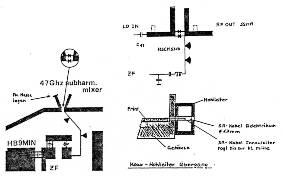
Figure 4: 47 GHZ Subharmonie Mixer
5. Lo-doubler to 23 GHz and 47 GHZ subharmonic mixer
The 47 GHz convener is roughly the same as the 24 GHz module. The main difference is the construction of the mixer, which has been chosen as a subharmonic mixer. This circuit achieves a conversion loss of 15 dB and has a maximum output power of 0.1 mW. That's not an optimal solution but works fine for the first trials on 47 GHz. A better solution would be to amplify the 23 GHz LO to 20 dBm (100 mW) and construct a doubler for 47 GHz. A power of 8 mW can be achieved. That's sufficient for a rat-race mixer on 47 GHz. First experiments into this direction have been undertaken by the author.
6. Construction and Tuning
Construction is roughly the same as for the 24 GHz module. The subharmonic mixer uses two beam-lead diodes with a very small junction capacity, i.e. the HP-HSCH5310 or even better the HPHSCH9101. The ouput can be constructed as a waveguide transition with a piece of UT85 semirigid cable with sleeve removed. Coaxial connector, which can be used, are the RPC65SS, SSMA, K-type, V-type or 2.4 mm connectors.
HB9MIN, Erich Zimmermann.