Combining of TWTs on 10GHz
Abstract: To get high power on 10GHz EME medium size TWT of the 25W class are combined to achieve an output power of 45 - 50W. This is done by waveguide Magic Tee as a summing device and some additional devices for gain and phase equalisation.
1. Introduction
The experience during the first EME-tests on 10GHz at HB9AGE shows that an output power of 25W is the bare minimum to hear the own echos with a 3m dish. Therefore you need a better equipped station on the other end to make QSOs successfully (HB9AGE completed the QSOs with WA7CJO (4m dish/200W) amd SM4DHN (4m dish/80W) in 10 minutes). To improve station performance you can increase the size of the dish, the power or improve the receiver. With a 0.7dB LNA sensivity is already limited by moonnoise. A larger dish is even more difficult to point. High power TWTs (>50W) are difficult to get. But 25W TWTs are available. The solution to 3dB more power is to combine 2 TWTs.
2. Combining Technique
The block diagram (Fig. 1) shows the necessary prerequisites:
- 2 x 25W TWT, same type, same brand
- 2 x power supply
- A good magic T for 10GHz. Be careful to get one for X-band and not for the 8.5 to 9.5GHz radar band
- 2 x wave guide loads for 50W
- 2x 10dB adjustable attenuator
- Line stretcher, piston type
- Low level power splitter
- 2x isolator, coax
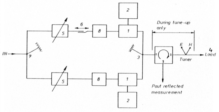
Figure 1: Coupling Block Diagram
2.1. General Notes
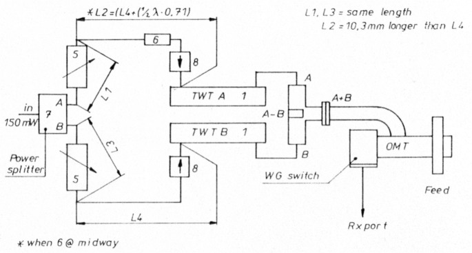
Figure 2: Coupling Schema
Fig. 2 shows the detailed setup. All the output lines up to the feedhom are waveguides. These have very low loss in comparison to Ur-141 semirigid cable. Don't waste your power in cables.
It's good practice to insert an isolator between the sum port of the magic-T and the feed. But these isolators introduce some loss (0.1 to 0.3dB) and are expensive. Isolators from surplus material are damaged sometimes. They exhibit high loss because of shocks - dropping on a floor for example.
The feed should have at least 20dB return loss. If you can't measure your feed I propose to insert an E/H-Tuner between the magic-T and the feedhorn. Tune the Tuner for maximum output to a high power load. The magic-T will provides a very good isolation to the tubes as long as it will 'see' a well matched and stable load.
The input of the tubes are fed via coax type isolators for smooth tuning and low interaction of the tubes. They provide a constant impedance to the tubes and isolate them from the attenuators and line stretcher.
Please keep in mind that any TWT has strong permanent magnets inside. When putting the TWTs on the same cooler allow for at least 30mm separation. Otherwise the focusing may be altered and power is lost or dissipation is increased. Avery large heatsink (<0.1K/W) should be used. The use of thermal compound is mandatory. My heatsink measures 25x40cm and has 25 fins each 5cm long. Two fans help for getting the heat off. A temperature of 60°C is achievable.
2.2 Construction Notes
My TWT's are installed right at the feedpoint with the power supplies at the back of the dish. Silicone insulated wires covered with urethane and shielded are used to connect the tubes to the supplies. I lost one expensive tube when using unshielded wire. Because of the strong RF-field nearly all DC-regulators get into malfunction.
2.3 Input Power Splitter
One can use any kind of device: 3dB hybrid, rat-race coupler, Wilkinson divider of 6dB resistor divider. The only point is that you can measure the same power on the two output ports. If you have enough drive select the resistor divider. With the hybrids you have to take into account that they have 90° phase shift. This must be compensated in the lengths of the input cables.
2.4 Variable Attenuator
The variable attenuators are used to normalize the gain in the two legs of the system. A simple proposal is presented in Fig. 4.1 used 200 ohms/sqcm resistive card for this design. In this simple design, attenuation and phase is changed if you move the card towards the wave guide center. This makes adjustment a bit tricky, because you have to readjust for the phase change any time you change the gain. It's important after tuning to lock the attenuators secure. An accidental change can screw-up the whole system.
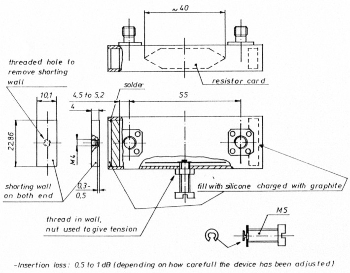
Figure 4: Waveguide Attenuator
A waveguide to coax transition is shown in Fig. 3. The have 30dB return loss. They have to be used if you have tubes with coax output, because the input of the magic-T is waveguide.
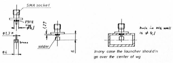
Figure 3: Coax to Waveguide Transition
2.5 Line Stretcher
The line stretcher or phase shifter is required to equalize the phase shift in the two branches. TWTs have phase shifts of about 3600 degrees. Line stretchers are difficult to construct. It's easier to get them from surplus. After all the line stretcher is adjusted to maximum sum output.
2.6 Magic Tee
A magic tee is the waveguide version of a 4 port 3dB Hybrid familiar in microstrip circuits. Fig. 5 shows that power present at input ports A or B will add at the sum port and subtract at the difference pon. As long as the signals are of equal magnitude and phase no signal will appear at the difference port.
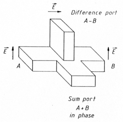
Figure 5: Ideal Magic Tee
To determine the characteristic of a real magic tee install the coax to waveguide transitions at the A and B ports. Install a waveguide load at the difference port, connect a coax load on port A and a powermeter on the other port B. Connectt some power to the sum port and measure the power on port A. Then interchange to Port B. Power output on both ports should be within 0.1dB. Isolation can be measured by connecting loads to the ports Aand B and measure the power on the difference port. A normal value of isolation is about 20dB.
One can drive the input ports of a magic tee with 180° out of phase signals also and take the sum power out of the difference port.
3. Tuning Procedure
Adjust the line stretcher to half way. Disconnect the magic tee from the tubes. With a load on the output, 40 dB directional coupler and a power meter adjust both tubes for the same power output by adjusting the attenuators. Interchange the power meter several times between the two tubes and verify that the power is stable. Fix the attenuators and reconnect the magic tee to the output. Connect one load, directional coupler and power meter to the sum port and the other measuring system to the difference port. Key down and one should notice more power on the sum port than on the difference port. Don't key longer than 5 seconds in the beginning. Adjust the line stretcher for maximum power on the sum port and for minimum power on the difference port. If the tuning limits of the line stretcher are reached, increase or decrease the line lengths in one leg and readjust the line stretcher to a medium position again. After successful adjustment the sum port must show about 2.8dB more power than a single tube and the difference port at least 20dB less.
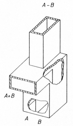
Figure 6: E-Plane Magic Tee
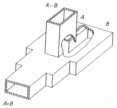
Figure 7: H-Plane Magic Tee
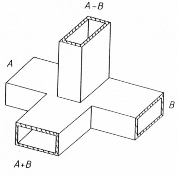
Figure 8: Standard Magic Tee
4. Acknowledgements
My thanks to Pierre, HB9CUA, for the drawings and to Lee Johnson for some ideas he inspired. Vielen dank an meinen Partner in der EME-Gruppe Pierre, HB9CUA, für die Zeichnungen und an Lee Johnson für einige Ideen.
5. Literatur
- "Broadband Phase Equalizing Technique for combining High Power TWTs", Microwave Journal, 12/1988
- "Power Combiner Supports 2W GaAs Amp at 35 GHz", Microwave Europe 11&12/1990
HB9AGE, Walter Hanselmann.