Unconditionally stable LNA for 144 MHz
This preamp for 144MHz exhibits low noise figure (0.3dB typical), moderate gain (18dB typical), excellent output VSWR (< 1.1:1), moderate input VSWR (< 5:1) and unconditional stability (K>1). It utilizes a MGF-1302 single gate GaAsFET, a helical coil in the input and a no-tune output circuit.
1. Introduction
Many designs for 144MHz preamps using single-gate GaAsFETs have been published in the past. But no unconditionally stable amplifier has been evolved up to nowt. This is true for the circuit of W6PO, which utilizes a 4:1 balun on the drain, and also true for a cascode circuit with a bipolar second stage and for simple resistive loading of the drain like in the circuit of YU1AW. Because of the low inherent stability of single-gate GaAs-FETs (K<0.1) it's not an easy task to stabilize this kind of device for unconditional stability.
Therefore the typical masthead preamp uses a dual-gate GaAsFET (TI-S3030 or AEG-CF300) with an inherent stability factor of 0.6. Then it's much easier to construct an unconditionally stable preamp. Noise figures of dual gate GaAs-FET preamps have been measured down to about 0.5dB NF with an associated gain of 23dB.
For those who think they need an even lower noise figure on 144MHz a single-gate GaAsFET must be used, which can provide noise figures down to 0.2dB. The secrets of a design which satisfies the requirements of a low noise figure and unconditional stability are both a low-loss input circuit comprising a high-Q helical coil and high-Q air trimmers, and carefully balanced stabilisation techniques which utilize lossless feedback in the source as well as dissipative stabilisation in the drain circuit. The optimum values of the circuit elements in the initial circuit design can be found by CAD-techniques utilizing simulation software.
2. Circuit description
The input circuit (Figures 1,8,14) is made as a helical coil with series and parallel variable capacitors for noise impedance matching. The helical coil can provide an unloaded Q up to 700, if properly constructed. The air trimmers used have a Q of 4000. Then the overall unloaded Q of the input matching circuit is something around 600. With an loaded Q of about 10 - see Fig.11 for a 3dB bandwidth of about 15MHz, which indicates a loaded Q of 10 - the loss introduced by the input circuit is less than 0.07dB. Therefore the total noise figure of 0.27-0.37dB is mainly determined by the device, which has a noise figure of 0.2dB-0.3dB. This indicates that a helical coil in the input is a good choice. If, for example, an input circuit with an unloaded Q of 200 was used, the resulting loss would be 0.22dB,whichsubsequentlywould result in an overall noise figure of 0.42-0.52dB. Therefore the single main influence on input loss is the quality of the input coil because the air trimmers have quality factors in excess of 4000.
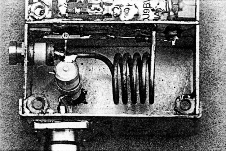
Figure 1: Top View on Prototype in small TEKO box
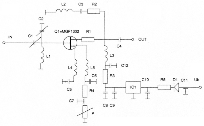
Figure 2: Circuit Diagram of LNA-144-1302
The output circuit is made from a series resistor R1, a parallel RLC-combination and a fixed tuned L/C-matching circuit. This provides broad-band matching of the output impedance of the FET and an increase in stability. No output tuning is necessary, because this circuit represents a low-Q circuit. An output return loss of better than 20dB can be achieved from 100 to 160MHz!
For stability in the LNA a mixture of lossy drain and inductive source feedback is used. L4 and L5 serve as the source feedback inductance. They are made from the legs of the MGF1302 (4mm free length and the series inductance of C4,5). This increases the stability factor on frequencies below 4GHz considerably, but must be applied with care because the stability factor above 8GHz is decreased. If the inductance is too large the preamp will oscillate above 8GHz. RI provides broadband series isolation and increases the stability factoi to a value above 1. For frequencies below 100MHz an additional stability margin is provided by L2/R2. All these stability measures decrease the gain from about 30dB down to 18dB and increase input retum loss from 0dB to 2.5dB.
| Part-No. | Type | Value | Manufact. | Manuf.-Code |
|---|---|---|---|---|
| C1,2 | Air-Trimmer | 1.2-10pF | TA,ATC | 5200 |
| C3,8 | SMD-C | 0.01 uF | Sie | 0805 |
| C4 | SMD-C | 82pF/NPO | Sie | 0805 |
| C5,6 | Trapez-Chip | 1000pF | ||
| C7,11 | Feedthrough | 1000pF | Sie | |
| C9 | SMD-Elko | 4.7uF/16V | Sie | 1210 |
| C10 | SMD-C | 0.1uF/100V | Sie | 1206 |
| C12 | SMD-C | 1000pF/NPO | Sie | 1206 |
| L1 | Helical Coil resonant with input compartment | approx. 200nH, Qo approx. 700 | 3.5 t. on 13mm Homebrew, ID, 17mm long, 2mm CuAg or 4.5 t. on 12mm ID, 13mm long 1.5mm CuAg | Sie Details in Fig. 7 |
| L2 | SMD-L SIMID01 | 2x100nH in Parallel | Sie | B62412-A3101-M |
| L3 | SMD-L SIMID01 | 470nH | Sie | B82412-A3471-M |
| L4,5 | Source Inductance | 4 mm Source Legs in free Air | ||
| T1 | FET | MGF-1302 | Mi | MGF1302-650-4 |
| R1 | SMD-R | 150 | Sie | 1206 |
| R2 | SMD-R | 56 | Sie | 1206 |
| R3 | SMD-R | 22 | Sie | 1206 |
| R4 | Metal-Film-R | 22 | ||
| R5 | Metal-Film-R | 47 | ||
| P | Trim-Pot Cermet | 100 | ||
| D1 | Diode | 1N4007 | Mot | |
| IC1 | Regulator | 78L05AC | Mot | |
| Bu1,2 | Coaxial Conn. | N-Male/BNC-Female | ||
| PCB | Output-Board | 35x72x1.54mm, ER=4.5 | DC3XY: Tel. (++49)410673430 | LNA144 |
| G | Box (Tinplate) | 74x55x30mm | Schu | |
| Kits and PCBs are available: Rainer Jäger, DC3XY, Breslauer Str. 4. W-2086 Ellerau | ||||
CAD Software allows Effective Design Work
After having determined the circuit topology the optimisation of the values of the circuit elements was carried out by means of SUPERCOMPACTPCI. This optimisation showed unambiguously that stability could not be achieved without the combined effect of R1, L4/L5 and L2/C3/R2. This can be seen in figures 3-7, which show the simulated stability factor and forward gain when omitting one of the circuit measures mentioned above. Interesting is Fig. 7: It shows a simple preamp without source feedback but with 50 Ohms resistive parallel to the drain. Even this circuit will not provide unconditional stability.
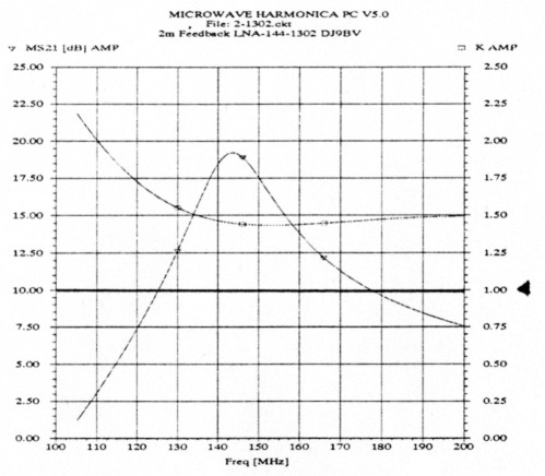
Figure 3: Simulated K-Factor and Gain - Final Design
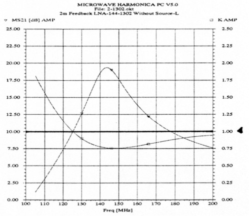
Figure 4: Simulated K-Factor and gain w/o Source Feedback
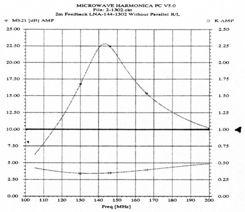
Figure 5: Simulated K-Factor and gain w/o Parallel R/L
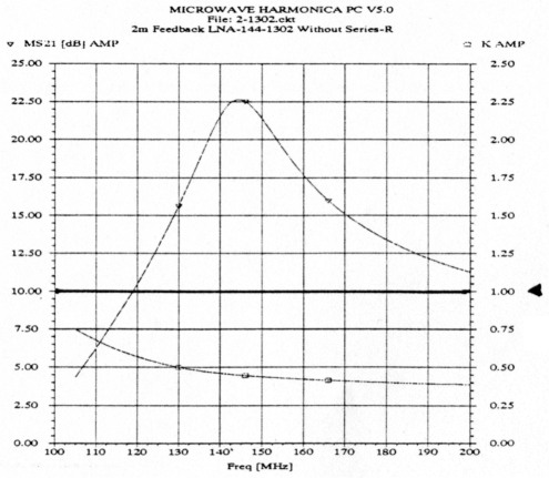
Figure 6: Simulated K-Factor and gain who Series-R
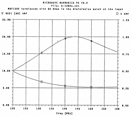
Figure 7: Simulated K-Factor and gain w/ 50 Ohms Load
A precondition for the validity of the simulation process was the knowledge of the S-parameters and noise parameters of the MGF-1302 at frequencies below 1GHz. These are not specified'by the manufacturer. The S-parameters have been measured and contributed by Dieter Briggmann, DC6GC. This proved to be a prerequisite for a successful stability analysis. Unfortunately the noise parameters were not available and had to be extrapolated 'intuitively'.
3. Construction
3.1 Mechanics
Construction is straightforward. Prepare box as shown in Figure 8. Prepare the PCB and solder all components to it (Fig. 9). Also the parallel trimmer should be soldered in. Attention: Don't use anything different than these 5200 type JOHAN-SON or TEKELEC trimmers because of their high Q and linear tuning, which allows for adjustment to minimum noise figure without having a noise figure meter. If you are forced to use different trimmers you need a noise figure meter for tuning, because you cannot set the series capacitor - see following advice on tuning! Solder the PCB to the separating wall so that the drain lug of the transistor can be fitted flat on the input stripline of the PCB. Finally mount the transistor to the circuit. It is important that the source leads have a free length of at least 4mm. The bottom cover has to be soldered to the side walls. Silvering the box is not a bad idea to get the maximum unloaded Q. Another important point is the contact between the cover and the box. For proper function of the helical coil a solid contact is required, because resonant currents circulate radially in the input chamber. The construction with a 0.1mm thick copper foil glued to a sheet of rubber inside the cover is mandatory for low contact resistance. Noise figure can increase up to 0.15db with bad contact. This kind of construction was selected only for easy access to the input chamber, but a seamless input resonator construction would be much better of course.
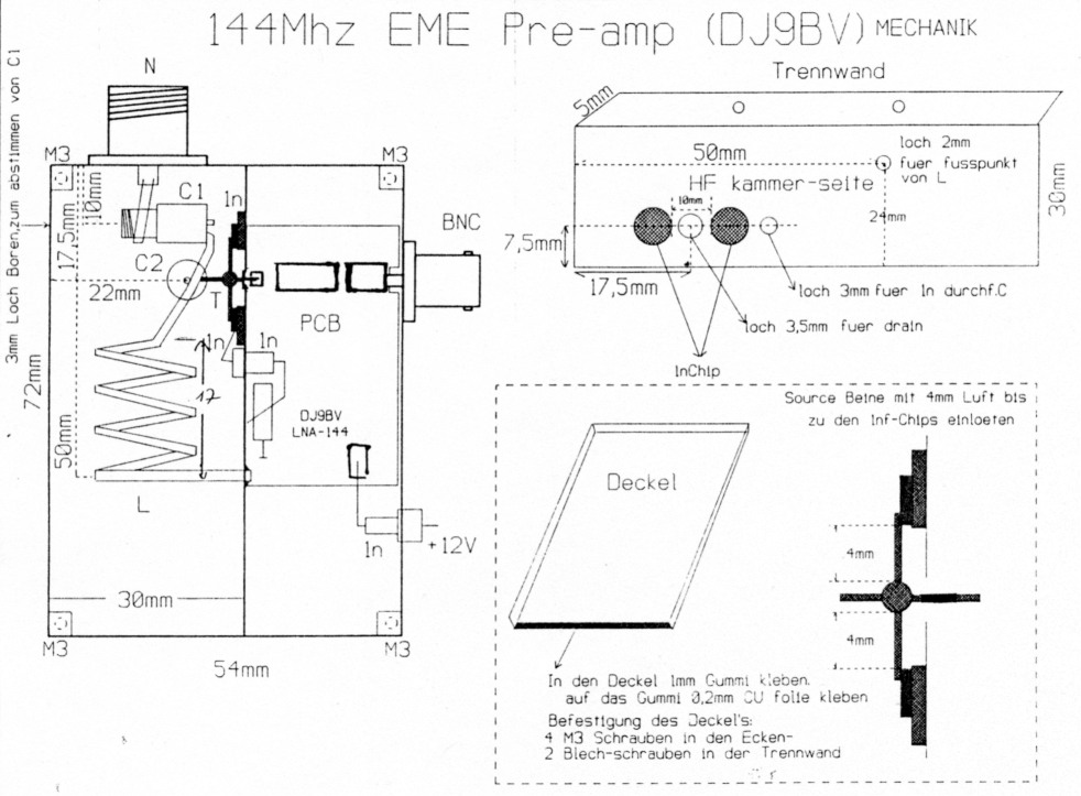
Figure 8: Box Construction LNA-144-1302
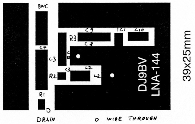
Figure 9: Top View on Output Assembly
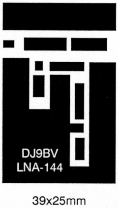
Figure 10: Epoxy-PCB of LNA-1441302
3.2 Initial Setup
For initial setup P1 is set to maximum value and supply voltage is supplied. Adjust Pl to a drain current of 12mA. Close the box (there must be a tight fit of the top enclosure to the separating wall and the sides), connect a noise figure meter and tune to minimum noise figure. Dependancy on drain current is nearly unnoticable for a range of 10-20mA.
If you don't have a noise figure meter, adjust both trimmers to minimum capacitance - tuning screw flush with the top of the trimmer. Then turn series trimmer exactly 3.5 rotations inwards - this
4. Measurement Results
Figure 11 shows the excellent output return loss of better than 25dB, a gain peak of 18dB at 146MHz and the input return loss of 2.5dB. Figure 12 indicates that the stability factor is well above 1 in the range between 100 and 300MHz. Therefore it can be guaranteed that this amplifier cannot oscillate. Fig. 13 shows the noise figure from 140 to 150 MHZ with a very broad minimum of approximately 0.3dB. This has been measured with HP8970B noise figure meter and a HP346A noise source which is specially made for measurement of non-impedance matched devices, i.e. GaAsFET amplifiers.
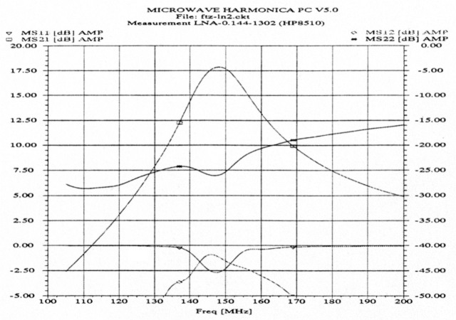
Figure 11: Measured S-parameters of LNA-144-1302
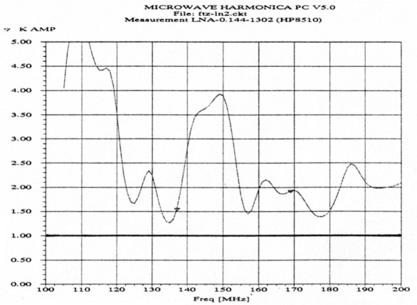
Figure 12: Measured K-Factor of LNA-144-1302
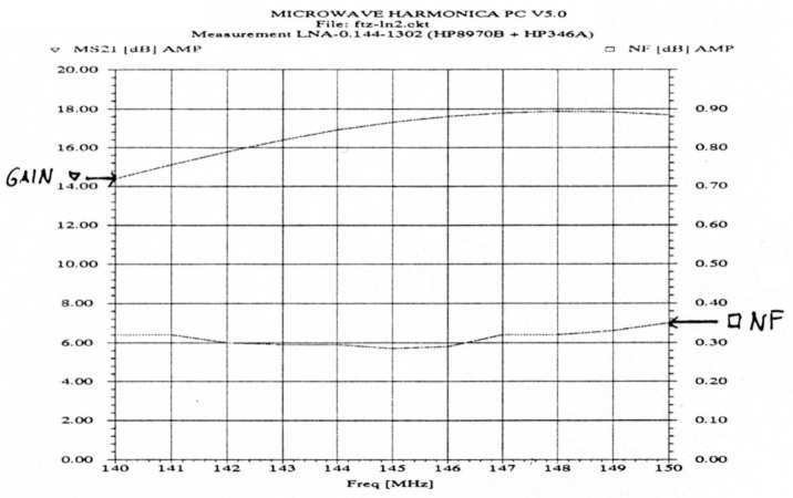
Figure 13: Measured Noise Figure and Gain of LNA-144-1302
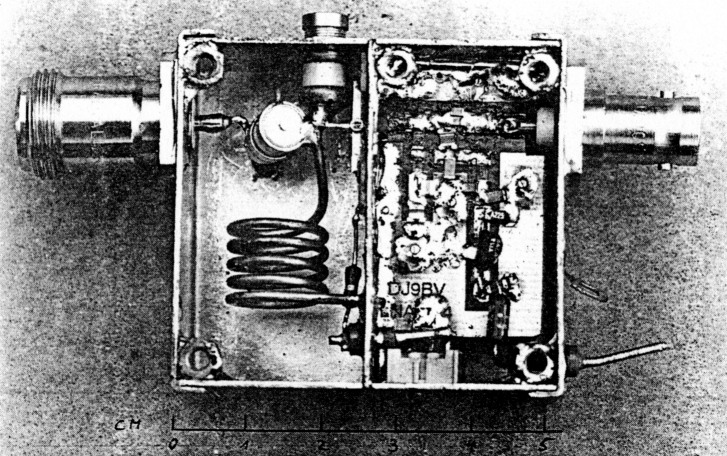
Close view on input circuit
5. Acknowledgements
I have to thank Klaus Eichel from TSS for lending the SC-Software; Christoph Petermann, DF9CY, for measuring noise figure and S-parameters; Fred Schulze, PE1DAB, for the nice construction drawing; Chris Ploeger, PA2CHR, for the the excellent photographs; and last but not least Dieter Brigg-mann, DC6GC, for measuring S-parameters of FEh on low frequencies. Without their help this work would not have been possible.
6. References
- R. Bertelsmeier, DJ9BV, "How to Use a Noise Figure Meter", DUBUS 4/1990, pp. 11-30
- R. Bertelsmeier, DJ9BV, "Low Noise Preamp for 1.3GHz", DUBUS 4/1991, pp. 37-50
- R. Bertelsmeler, DJ9BV, "144MHz Preamps: A Review", DUBUS 4/1992, pp. 29
- D. Dobricic, YU1AW, "Absolut Stabile, Rauscharme GaAs-FET Vorverstärker", UKW-Berichte 2/1990, pp. 118-126, 3/1990, pp. 138-146
- S. Sutherland, W6PO, "Some GaAs-FET Preamplifiers", EIMAC EME Note AS-49-31
DJ9BV, Rainer Bertelsmeier.