Locking VCXOs to 10 MHz
Any frequency universal version
Following a previous articie where this circuit with a CPLD was used to implement a PLL scheme that could lock one VCXO to a 10 MHz reference, this short articie describes a different approach to the locking method, resuiting in the possibility of locking only the least significant digits of any VCXO frequency making this circuit truiy universal without need for specific configuration files as in the previous design.
Introduction
The circuit described in this article uses exactly the same hardware as the previously published reference lock circuit(1) and consequentiy the same pcb and components (exception made for the resistors and capacitors forming the loop filter that should have their values adapted to this particular application).
The circuit is built around an ALTERA device EPM3064ATC44-4 that is configured to implement a low division ratio sampling PLL.
The used device, the EPM3064ATC44-4, (the -4 denotes 4 ns delay) can operate directiy at above 180 MHz of clock, being the actual maximum frequency dependent on the complexity of the circuit configured inside the CPLD, that in our application sets the limit near 165 MHz, therefore being useful to lock a VCXO safely up to 150 MHz.
Circuit description
The reference signal, presumably 10 MHz (although other reference frequency could be used), is divided down to the desired comparison frequency. The reference division value can be selected externally by choosing one of the eight possible configurations. Therefore we are abie to select one of the eight comparison frequencies configured. This comparison frequency is used to digitally sample the VCXO signal resuiting in a downconversion to the nearest multiple of the comparison frequency. When in the lock state the downconversion is effectively done to DC and provides an error signal to the VCXO frequency correction. In very practical terms this circuit appears to lock the least significant digits of the frequency of the VCXO being the most significant digits left unchanged.
For example a 96 MHz VCXO being set to 96.00 MHz ± 5 KHz would be lock to 96.00000... MHz with as many precision digits as the actual reference signal provided to the circuit (this happens for both 10 KHz and 100 KHz lock frequency).
The reference frequency selection (hence the lock points) is done by setting the 3 configuration bits allowing up to 8 different lock points. The values configured should cover most of the needs and are presented in the tabie below:
- conf = 000 locks to the nearest 10 kHz multiple
- conf = 001 locks to the nearest 100 kHz multiple
- conf = 010 locks to the nearest 2.5 kHz multiple
- conf = 011 locks to the nearest 25 kHz multiple
- conf = 100 locks to the nearest 3.3333... kHz multiple
- conf = 101 locks to the nearest 33.33333... kHz multiple
- conf = 110 locks to the nearest 5 kHz multiple
- conf = 111 locks to the nearest 50 kHz multiple
Loop filter
The use of lower comparison frequencies and also extremely high gain (phase/voltage) at the phase comparison require the loop filter characteristics to be set accordingly. lt can be calculated exactly to best performance and fast response however this would require to have the phase response and reference plus dividers intrinsic jitter very well characterized which would not be an easy task. The first approach can be done using the usual loop filter calculation for classical analog PLLs followed by trial and error optimization. The loop filter optimization should be done for the best compromise between speed and resuiting phase noise at the VCXO. Another possibility would be to trust the inherent phase noise of the VCXO and make the loop filter several orders of magnitude slower than required. This last option will result in reduced lock range being the 010 configuration the most unfavorable.
The use of 100 kHz, 50 kHz lock points are the most favourable ones and should be used whenever possibie. This allows a broader loop filter and consequentiy faster lock times and broader lock range.
Typical values for the R and C are: R1=100K R2=47K C1=470nF C2=4.7µF(tantal).
Conclusion
This universai VCXO lock version presumably covers all frequency arrangement needs for the microwave and millimeter wave converters, and is therefore preferable to use over the previous version. Also, due to the low division rate in the VCXO signal path it can be beneficial to reduce even further the close in phase noise of the VCXO if an optimum loop filter is provided.
Exception should be made if the lock ranges are pretended to be large or assurance that you are locking in the correct frequency can not be done by other means, where the classical PLL version(1) should be used, (this is however not the situation of most VCXO where the tuning range is about ± 1kHz at 100 MHz, and therefore no possibility for it to lock on the next lock point 100 kHz or 50 kHz above or below the desired frequency).
Hardcopies of the PCB's at 4:1 scale, diagrams and ready to program *.pof and *.jam files can be found at my web page. Thanks to all that helped with ideas info and components. lf after this universal version you still have specific configuration needs mail me.
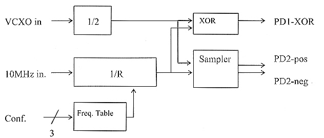
Fig 1 - Block diagram of the logic implemented inseide the EPM3064.
Reference
- Locking VCXOs to 10 MHz for the Microwave and mmWave local oscillators. - L. Cupido - DUBUS 3 / 2002, p. 13
Luis Cupido, CT1DMK