High stability local oscillators for microwave receivers and other applications
Phase-locked approach offers greater stability
This article describes a reliable phase-locked loop originally designed for the first conversion of a radio astronomy microwave receiver(1) applicable for general microwave receiver use and to other HF, VHF, and UHF phase-locked applications as well.(2) Its design evolved from one of my earlier efforts incorporated in a fully synthesized, general coverage HF transceiver as shown in fig. 1.
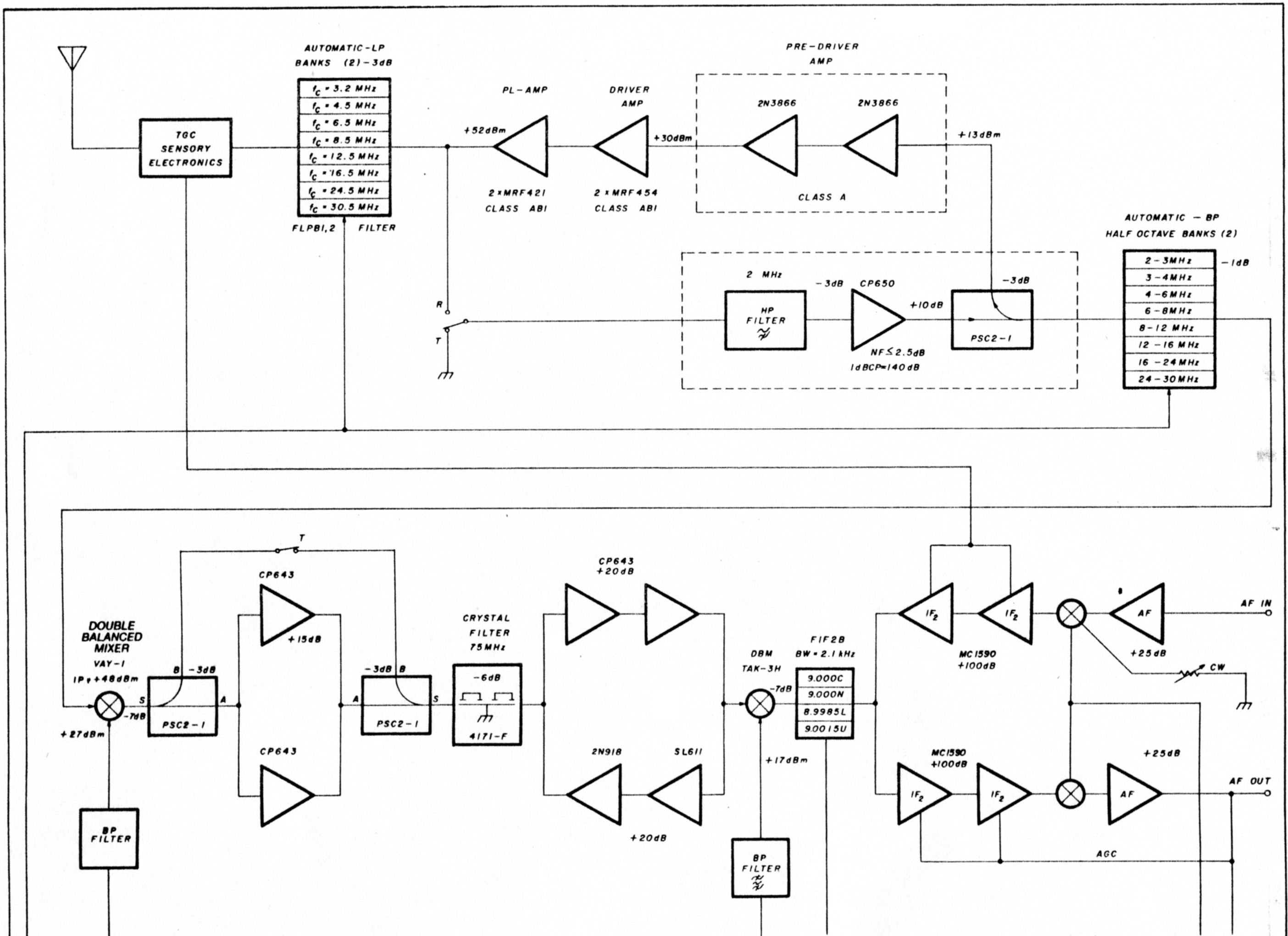
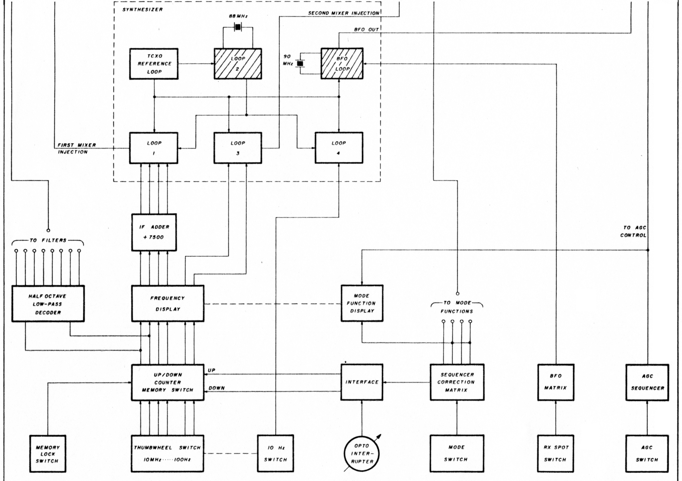
Fig. 1. Application of fixed VHF phase-locked-loops in a fully-synthesized HF transceiver. The VHF loop described here is used twice (88 MHz end 90 MHz for the BFO) in order to ensure full synthesis for the entire radio.
Local oscillators used for conventional microwave (TYRO) such receivers are usually open loop and are installed outdoors as part of the first converter, known as the "head end" and located at the feed point of a parabolic dish antenna. They normally exhibit gross frequency instability (typically ± 1.5 MHz) due to their free running characteristics, which are affected by ambient temperature changes as well.
The two types of open-loop local oscillators most commonly used for this application are the free running tuned cavity and the crystal controlled multiplier type. This article deals with the second approach, which allows an already-clean multiplier chain to lock on a much more stable reference frequency strategically located away from the elements. Consequently, the unit can be used under varying temperature conditions and will follow a remote reference source kept indoors for good stability.
The synthesizer uses a simple version of a type-one crystal-controlled phase-locked-loop operating at 88 MHz.(3) Its output is divided by a fixed modulus divider involving emitter-coupled-logic (ECL) and transistortransistor-logic (TTL) circuits. The division number N is fixed at 88 and followed by an exclusive OR digital phase detector that closes the loop through a simple low-pass filter as shown in fig. 2.
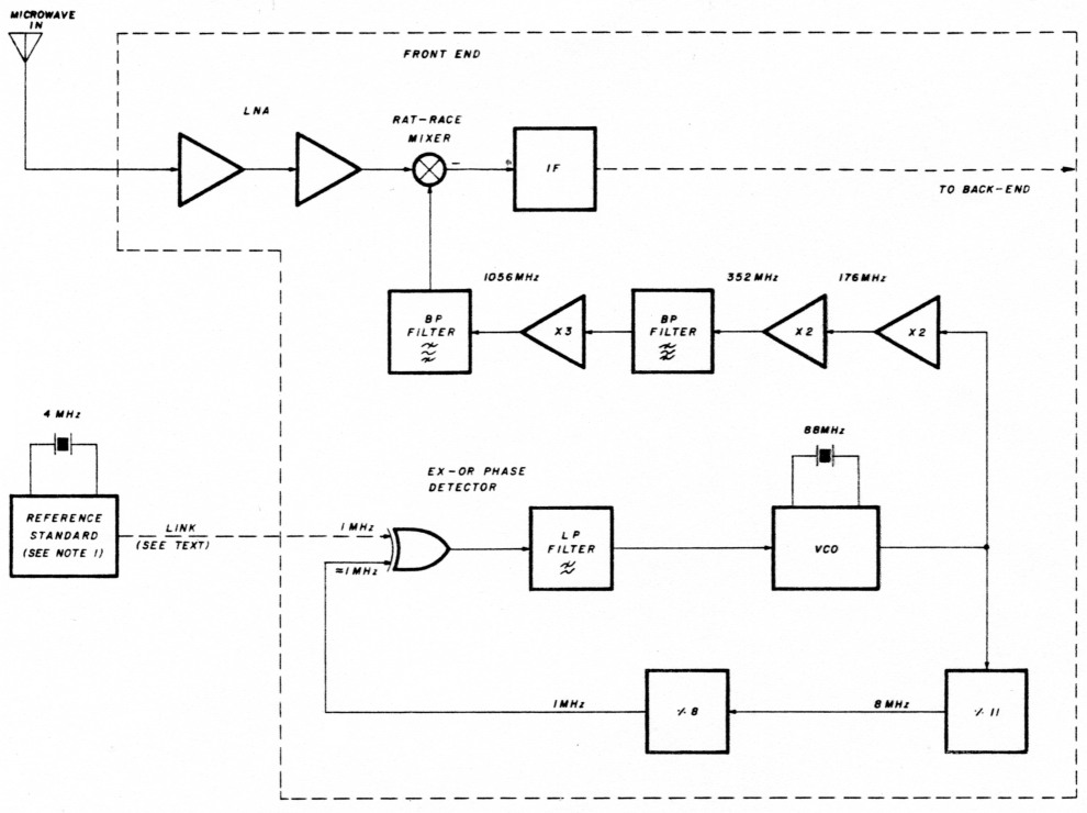
Fig 2. Block diagram of the phase-locked-loop as used in a stable microwave local oscillator located at the low noise block converter (LNB) outdoors. The 1 MHz reference frequency is derived from an indoor TCXO.
In order to obtain the desired microwave frequency, the output of the oscillator running at exactly 88 MHz is used to drive a times-12 multiplier such as described by Paul Shuch, N6TX.(4) Other multiplications are possible for even higher frequencies. The reference frequency can be supplied to the synthesizer from the back end of the receiver via fiber optics or coaxial cable communication links (depending on the distance; digital line drivers may be required in the latter). With this approach, a remotely located temperature-compensated crystal oscillator (TCXO) that acts as a time base will maintain the short and long term frequency stability of the 88-MHz crystal oscillator through the phase-locked technique. The stability of the multiplier chain in the microwave receiver will thereby also be favorably affected. High initial stability and spectral purity would be required to compensate for the magnifying effect of the multiplier. My circuit used a 4-MHz TCXO manufactured by McCoy Electronics for the reference oscillator. This part guarantees ± 5 x 10⁻⁷ (±0.5 PPM or ±2 Hz at 4 MHz) Hertz per year.(2) This represents an ultimate stability for the remotely located L-band local oscillator of ± 6 Hertz, respectively.
Figures 5A and B show the "brassboard" of the synthesizer and how phase locking was maintained under freezing conditions. For convenience a lock indicator was incorporated in the design as shown in fig. 3.
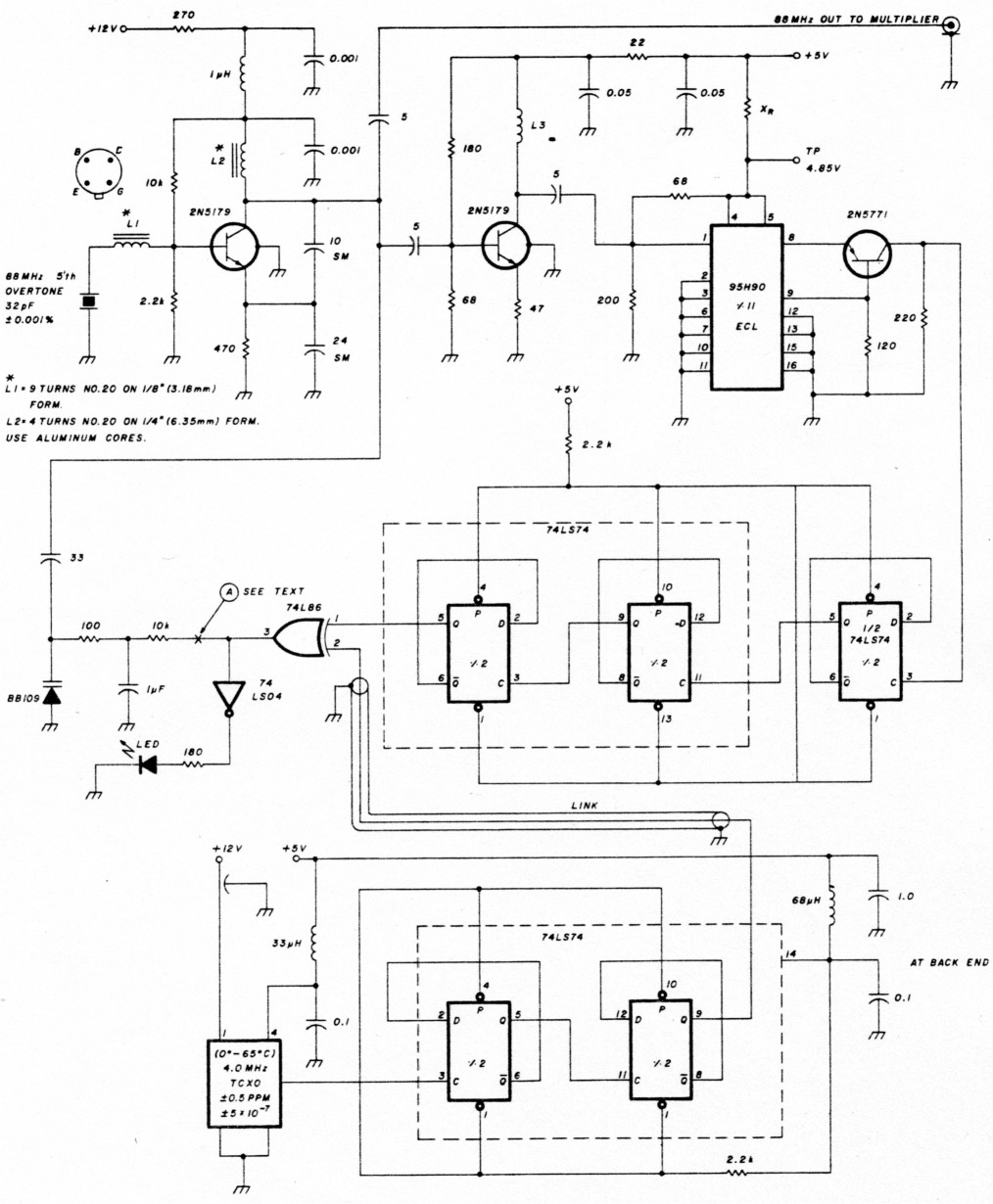
Fig. 3. Circuit diagram of the phase-locked-loop. A fifth overtone series-tuned Colpitts oscillator was chosen for stability. The design results in simple and effective exclusive OR phase detectors and low-pass filter. The relatively high 1 MHz reference allows for clean and stable LOs (see text).
The circuit design of the synthesizer is simple (although making one work is another story) as shown in fig. 3. A highly stable 88-MHz (0.001 percent) fifth overtone crystal was chosen to guarantee initial startup almost on frequency before locking occurs. It is used in a series resonant Colpitts oscillator with one side of the crystal grounded. I selected the Colpitts design because of its well known circuit stability and predictability.(5) The output of the oscillator is then amplified and converted to the ECL level required by the 95H90 divide-by-11 device.(6)(8)
An ECL-to-TTL level shifter circuit follows the 95H90 and additional division is obtained with three divideby-2 sections of 74LS74 devices.
The divided-down 1-MHz input to the phase comparator 74L86 (slow L logic was chosen here to keep the output as quiet as possible) is compared against a true 1-MHz reference available from the back end. The exclusive OR phase detector was chosen as a perfect application for this type of phase-locked-loop because the crystal controlled Colpitts oscillator is guaranteed to start almost on frequency and within the capture range of this particular type of phase detector which is only 2π.(2)(3)(7) Other important criteria for choosing this type of phase detector were the 50 percent duty cycle of the signals present at its inputs and the high reference frequency (1 MHz), all design requirements for successfully using an exclusive OR gate as a phase detector.(7)
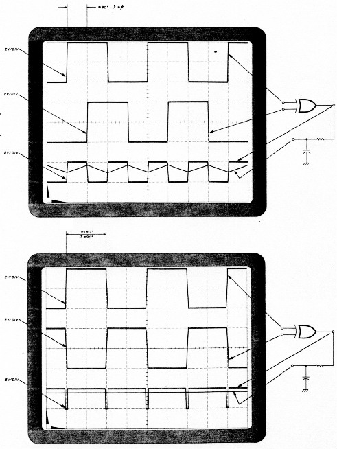
Fig. 4. (A) Locked condition. (B) Out-of-lock conditions for a synthesizer using the exclusive OR phase detector. The output of the low-pass filter is a 2.5 volts DC signal (see text).
When the loop is locked, the output of the phase detector is a 50 percent duty cycle square wave at twice the reference frequency; in this case it is 2 MHz as shown in fig. 4. This output is averaged by the simple RC low-pass filter with a corner frequency (ωn) of about 16 Hz and is finally presented to the Amperex varactor diode BB-109, which acts as a variable capacitor steering the crystal oscillator in lock. Under locked conditions, the averaged DC output of the phase detector equals half of the TTL supply voltage, or about 2.5 volts DC. When this occurs, the divided 1-MHz signal present at one of the phase detector inputs lags and a reference 1-MHz signal present at the other input by approximately 90 degrees (delay is introduced by the additional circuitry) which corresponds to a zero phase error.(3) The secret of the entire circuit is L1 and L2, which are calculated to resonate the Colpitts oscillator on the fifth overtone of the crystal. Additional "tweaking" may be required to bring the circuit into resonance due to local stray elements. High Q aluminum cores were used in my prototype for best results.
Adjustments
With the loop line disconnected at A (see fig. 3), inject a 2.5 VDC level at the 10 kilohm resistor (which is part of the low-pass filter. The best way to do this is to use a couple of batteries in series through a 10-kilohm linear potentiometer voltage divider to insure a pure DC voltage. With the circuit board heated to 80-degrees F (a 100-watt lamp on top of the circuit will do well), adjust L1 and L2 for resonance at the fifth overtone of the crystal as measured on a frequency counter. Observe the position of the cores. Cool the circuit to -78 degrees F with a dry cooling spray. Adjust L1 and L2 again for resonance. (The circuit should still work at this temperature; according to calculations, the transistor junctions will reach only about -40 degrees F.) To accomplish this, selected parts have been used in the prototype. Again, observe the new position of the cores.
Wait until the circuit returns to room temperature and readjust L1 and L2 midway between the two positions. Remove the 2.5 VDC voltage from the low-pass filter and reconnect the loop back at A.
The circuit should now lock every time power is turned on and lock should be maintained over the entire temperature range. This can be verified through repeating the above procedures with the loop closed.
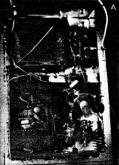
Fig. 5. (A) The synthesizer circuit was frozen to -78 degrees F with cooling spray.

Fig. 5. (B) After calibration the phase-locked-loop remained locked over the entire temperature range. The divided 1 MHz square wave shown at the top follows the reference frequency at the bottom by -90 degrees, which represents a 0 degree phase error (see text).
An out-of-lock condition would be indicated by the blinking LED, should recalibration become necessary. If the circuit is to be used at room temperature, such as in an HF or VHF/UHF receiver, no indicator should be required. Other status reporting features are possible and can be remotely monitored at the back end of the microwave receiver.
This synthesizer represents an effort of several weeks of design and "brassboarding." It began with the use of a 54S124 dual VCXO integrated circuit that was intended to work at 85 MHz, but was not successful for my application because of the crystal frequency restrictions and the limited upper frequency range for this device.
The new design will work to about 140 MHz (1680-MHz LO output when used with the N6TX multiplier, and beyond with other multipliers). Its limitations are the fabrication of crystals at VHF frequencies and the rather small size of L1 and L2 at the higher frequencies.
This design represents a practical approach to clean and stable local oscillators. Phase and amplitude noise have been measured to be at least -70 dB/Hz at ± 100 Hz from the desired carrier (see fig. 6). Discrete spurious components were better than -60 dB, while the wide band noise was at least -70 dB measured with a 10-kHz bandwidth.
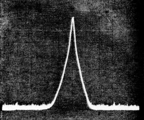
Fig. 6. Spectrum analyzer tests performance of the phase-locked-loop.
These specifications depend on the application of sound RF design techniques and may vary according to the circuit components selected. Although a synthesizer layout is not provided in this article, compartmentalization of modules in a true "synthesizer fashion" is highly recommended.
As suggested at the beginning of this article, other than microwave applications of this synthesizer are possible. Among them are beat frequency oscillators (BFO) and fixed oscillators used in multi-loop fully synthesized HF and VHF/UHF receivers and transceivers, as shown in fig. 1. Figure 7A shows the block diagram of a 9-MHz BFO application as used in my HF transceiver. Figure 7B shows the circuit details of the digital to analog portion of the BFO which provides the proper injection to an active product detector/ modulator in my transceiver. Many other applications are possible.
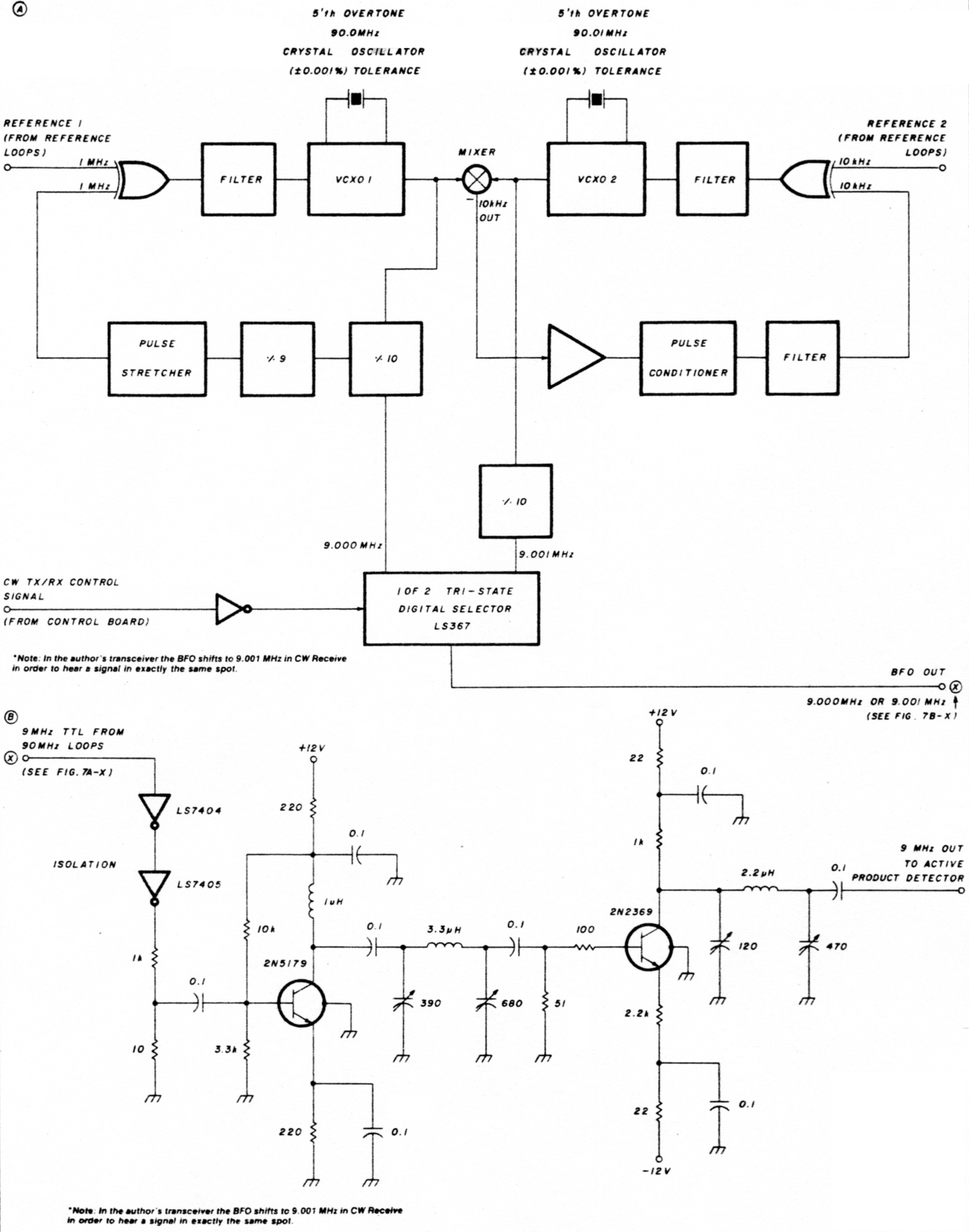
Fig. 7. (A) Block diagram of an elegant 9 MHz BFO as used in a fully synthesized HF transceiver. The signal is derived from a dual 90 MHz phase-locked-loop similar to the one presented here (see text). (B) Signal processing for the 9 MHz BFO. The 90 MHz derived signal is conditioned before it is applied to the active mixer product-detector/modulator.
Notes
- Among many ECL dividers, the 95H90 or its equivalent, the Plessey SP8640 can be programmed to be divide-by-10 or 11, or both in high resolution dual modulus phase-locked-loops.(2)
References
- Cornell Drentea WB3JZO, "New Trends in Communications Technologies: Radio Astronomy and the Search for Extraterrestrial Intelligence," ham radio, March, 1985, page 10.
- Cornet Drentea WB3JZO, Radio Communications Receivers, TAB, 1962, pages 158, 165, 168, and 181.
- E. Roland Best, Phase-locked Loops, Theory, Design, and Applications, McGraw-Hill, New York, 1984, pages 70, 74, and 156-164.
- Paul H. Shuch. N6TX, "Compact and Clean L-band Local Oscillators," ham radio, December, 1979, page 40.
- Herbert L. Kraus, Charles W. Bastian, Fredrick H. Rabb, Solid State Radio Engineering, John Wiley & Sons, 1980, page 159.
- Marion D. Kitchens, Jr., K4GOK, "VHF Prescaler for Digital Frequency Counters," ham radio. February, 1976, page 32
- Ulrich L. Rohde, DJ2LR, Digital Pll Frequency Synthesizers, Theory and Design, Prentice-Hall, 1983, page 209.
- VHF 300-MHz Prescaler, Application Note, Fairchild, 1979.
WB3JZO, Cornell Drentea.