Two-tone signal generator
Check linearity of SSB transmitters with an easy-to-read oscilloscope display
This article describes a two-tone test generator for checking SSB transmitter linearity. In addition to supplying two low-distortion audio tones to the microphone input of a transmitter, it has three additional features. The first permits the generation of a "bow tie" display on an oscilloscope in which linearity shows up as a straight line, which is easily judged, rather than as two interlaced sine waves, which are not so easily judged. The second feature modulates the level of the two tones at a pseudo voice rate, permitting operation at voice average power levels while viewing a two-tone. (Some transmitter power supplies "droop" during single-tone or even two-tone operation, reaching their peak power output only with a voice waveform with its corresponding low average power.) The third feature is crystal control of the frequencies, which permits accurate frequency measurement of a transmitter without the necessity of generating the carrier.
This generator was conceived as a school project almost 20 years ago. Assigned to build a circuit board, we made a two-tone generator that used two twin-tee oscillators, with the high oscillator locked to the third harmonic of the low oscillator with a small capacitor. When the output of the low oscillator, through a phase shift network to compensate for phase shift in the transmitter, was fed to the X input of a scope and the transmitter output was fed to the normal Y input, a "bow tie" pattern resulted, making judging distortion easy. But the tones had significant distortion and the third harmonic lock was unstable. Over the years I tried to improve it by various means, including the use of function generator ICs. This design, which offers maximal features but minimal complexity, is the final product.
Operation
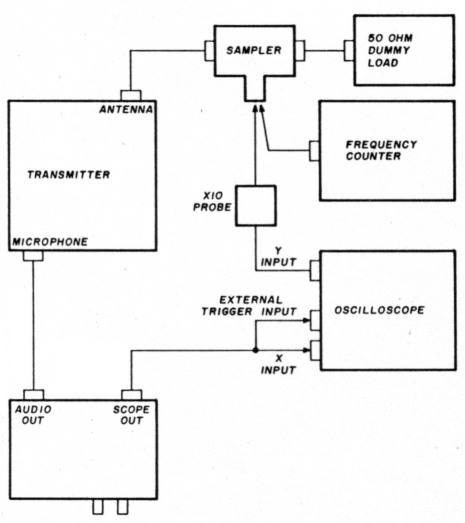
Fig. 1. Test connections, two-tone test generator to transmitter.
For normal operation the output is connected to the microphone input or phone patch input of the transmitter (see fig.1). The oscilloscope is usually connected to the RF output via an X10 probe; the RF output is then connected to a 50-ohm dummy load. Turn the transmitter and the test generator on and adjust the balance and level controls for minimum valleys and peak output as shown in fig. 2A. The switches should be in the "normal" and "600 Hz" positions. The scope output may be connected to the "external trigger" or "channel B" input to the scope and used to synchronize the display. Varying the phase control will shift the display horizontally.
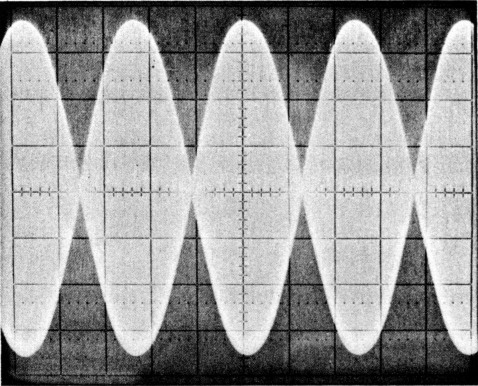
Fig. 2A. Output of a commercial transceiver, standard two-tone pattern.
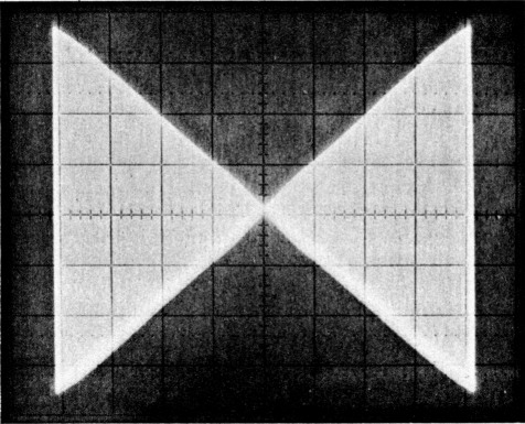
fig. 2B. Output of a commercial transceiver, bow tie pattern.
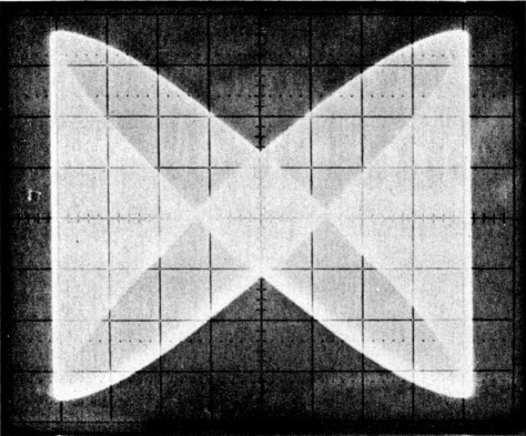
Fig. 3. Bow-tie pattern before adjustment of phase control.
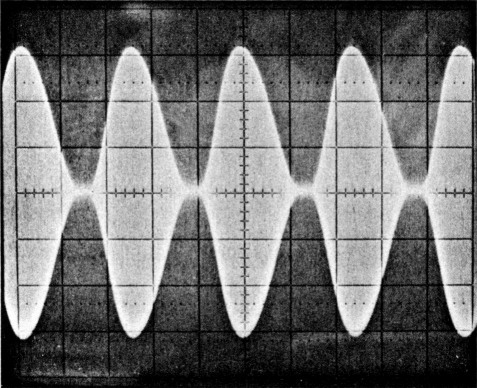
Fig. 4A. Severe crossover distortion, standard position.
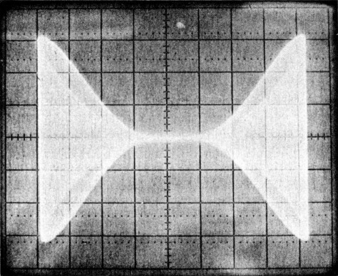
Fig. 4B. Severe crossover distortion, bow-tie pattern.
For a "bow tie" pattern, shift the scope output of the generator to the X input of the scope. Adjust the X channel gain for full horizontal display. With the transmitter on, a pattern similar to fig. 3 should occur. Rotate the pattern with the phase control to produce a "bow tie" pattern similar to the one shown in fig. 2B. (Figure 2B was taken with a commercially built Amateur transceiver and appears to be perfect, yet slight variations in linearity are clearly visible in the "bow tie" pattern of fig. 2B.) Figure 4A shows a pattern produced by a transmitter with severe crossover distortion caused by low screen grid voltage and fig. 4B depicts the same with a "bow tie" display. Figures 5A, 5B, 6A, and 6B show two different kinds of distortion and the resulting patterns.
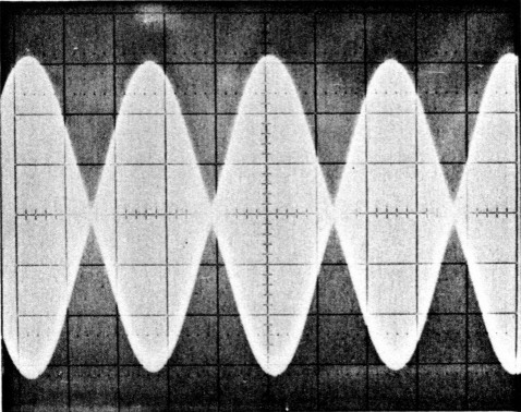
Fig. 5A. Minor distortion, higher levels emphasized, standard pattern.
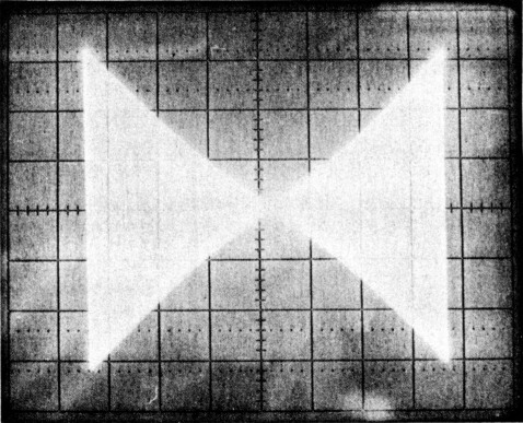
Fig. 5B. resulting bow-tie pattern.
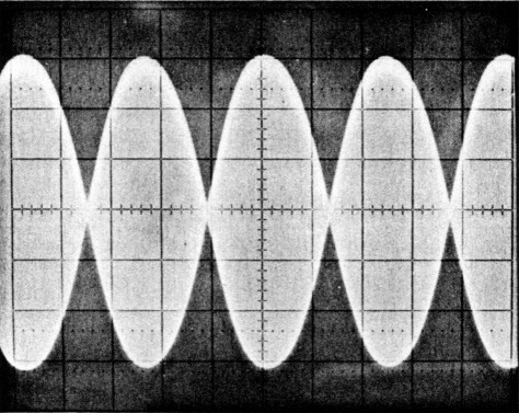
Fig. 6A. Minor distortion, higher levels deemphasized, standard pattern.
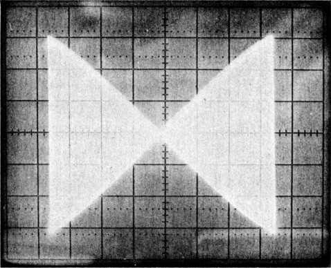
Fig. 6B. Resulting bow-tie pattern
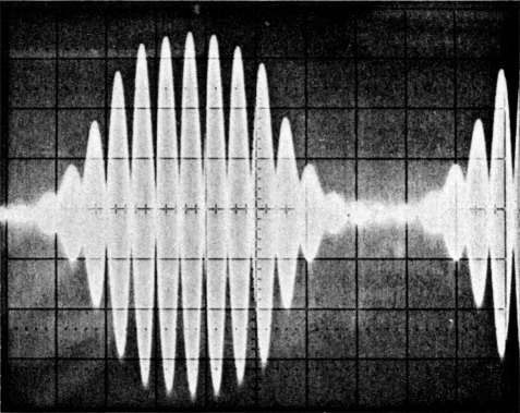
Fig. 7. Pseudo voice pattern using "Modulated" functions.
Figure 7 shows a display using the "modulated" feature to reduce the average power to that encountered during modulation. The synch switch is changed to 75 Hz to synchronize the display. Relative power levels for each mode as measured on a commercially built Amateur transceiver are shown in table 1.
| Single tone | 120 watts |
| Two-tone | 60 watts |
| Two-tone, pseudo voice | 15 watts |
| Voice ("e" as in "hello" | 15 watts |
| Voice, as above, 20 dB compression | 50 watts |
For precise frequency measurement, a single tone is fed into the transmitter. The audio frequency is added to (for LSB) or subtracted from (for USB) the counter reading to arrive at the correct carrier frequency.
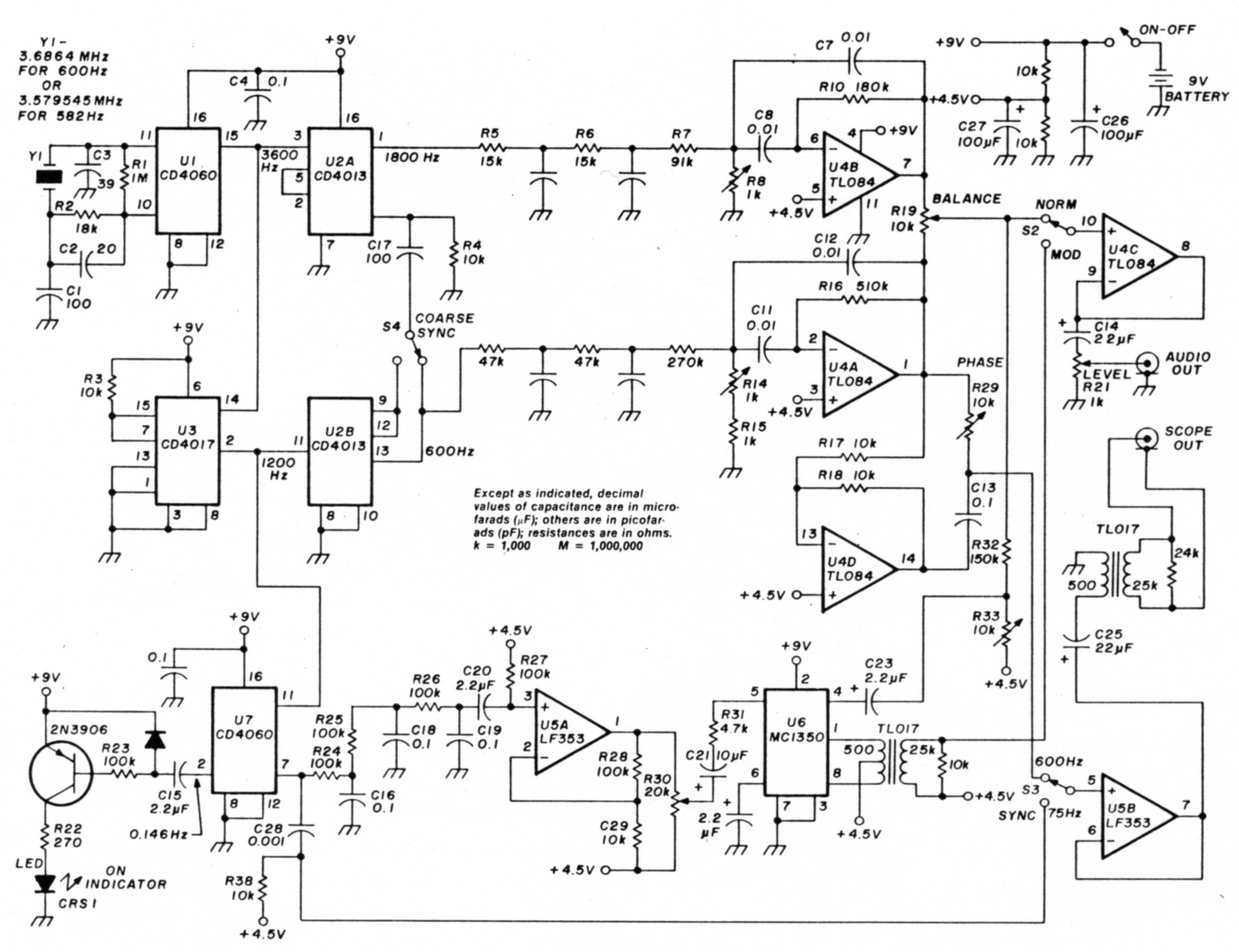
Fig. 8. Schematic of two-tone test generator.
Theory, digital section
U1, a CD4060, contains an oscillator and a 14-stage binary divider. Y1 can be either a 3.579545 TV crystal (producing output frequencies of 582 and 1746 Hz) or a 3.6864 crystal (producing output frequencies of 600 and 1800 Hz). The tenth binary stage puts out a 3600 Hz square wave, which is fed to U3, a CD4017 decimal counter set up to reset on the third count, resulting in a 1200-Hz asymmetrical square wave.
Both the 3600 Hz signal and the 1200 Hz signal are divided by two by U2 to produce 1800-Hz and 600-Hz symmetrical square waves. The 1800 Hz signal is locked to either the leading or trailing edge of the 600 Hz wave via differentiator C17 and R4, which triggers the reset input of the 1800 Hz divide-by-two section. S4 permits triggering from either the Q or Q output of the 600-Hz divide-by-two. This insures that the generator will always start up with the same phase relationship and permits changing the phase 180 degrees to compensate for the less-than-360 degree phase shift available from the "fine" phase control. U7 further divides down the signal to provide 75 Hz for the modulator and 0.146 Hz for the LED "on" indicator. The LED flash provides a visible indication of the operation, yet avoids the 10- to 20-mA drain of a steady lamp.
Theory, analog section
R5, C5, R6, and C6 provide two poles of lowpass RC filtering to reproduce a near sine wave of 1800 Hz. I've found that when converting a fixed frequency square wave to sine that multiple RC lowpass sections, operated well beyond cutoff and followed by an op amp to recover gain, is simple and effective. In this case, very low distortion is needed so U4B is configured as a multiple-feedback bandpass filter. U4A is set up similarly, but for the 600 Hz channel. The series resistors in the RC sections may have to be changed slightly to adjust for equal gain through each channel and/or set the output of the bandpass filters to approximately 1 volt RMS. Both signals are mixed together at the balance potentiometer and go to the the transmitter through a voltage follower, U4C, and the level control. Up to this point, the circuit is similar to any conventional two-tone generator.
To obtain the "bow tie" pattern, the low tone must be sent to the X channel through a phase shifter to compensate for phase shift in the transmitter. U4D inverts the 600 Hz tone and feeds one side of phase shift network C13 and potentiometer R20. Nearly 360 degrees of phase shift is possible. Voltage follower U5B presents a high impedance load to the output of the phase shift network and drives the scope isolation transformer, T1. Note that the secondary of T1 is kept floating from the chassis. Without DC isolation, severe problems with ground loops often occur. Care must also be taken with oscilloscopes that have a simple X input because they can be easily overdriven by the several volts available at the scope output. A 500-ohm to 500-ohm transformer could be used as well.
To provide the modulated function, the 75 Hz square wave is converted to a near sine wave by three poles of RC filtering followed by gain recovery stage USA. The 75 Hz signal enters the AGC input of U6, varying the output at a 75 Hz rate.
Construction
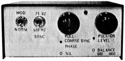
I built the prototype using perf board, IC sockets, and point-to-point wiring using 30 gauge wire. Later I made a circuit board. Either way works fine. In the unit shown (see photo 1), I used some exotic dual-section pots with push-pull switches from my junk box, but normal pots will work just as well. I also added an extra 9-pin plug to allow the use of individual adapter cables to various transceiver microphone inputs and a switch to key the transmitters on. The case, battery holder, and switches came from Radio Shack. Mylar capactors should be used in the filter sections and the phase shift network. The 0.1 µF capacitor shown in the power supply line should be placed directly across pin 16 and 8 of U1.
Alternatives
One alternative that might be tried is using a 32 kHz watch crystal. In this case, R1 should be changed to 10 Megohms and R2 to 680 or 750K. Only four stages of binary division would be required to produce 4096 Hz at the input of U2A, resulting in input tones of 2048 Hz and 682.66 Hz. The TL084 and LM353 ICs were used because they produce very little distortion. An LM324 and an LM348 could be used if resistors were added from the output of each amp to either ground or Vcc to cause the IC to always supply current in one direction. The crossover glitch is very visible on a sine wave. Don't omit the load resistors on the transformers; if you do, significant distortion will result.
If you want to operate the two-tone test generator from an external AC or DC supply, or to ground the case to some external test equipment, an isolation transformer must be added to the audio output. In this case, T1 would not be needed, and the scope could be driven directly from voltage follower U5B. I tried this in one case and it worked fine. Again, don't forget to to terminate the transformer correctly! The power supply can be anything from 8 to 14 volts but must have very low ripple. I would recommend a three-terminal regulator in this case.
Testing the circuit
Plug in the digital ICs. Use some form of current limiting in the power supply - to begin with, a 10-ohm resistor in series with a battery or a current limiting power supply. Turn the unit on and determine that normal current is flowing. Check for 3600 Hz, 1800 Hz, 1200 Hz, 600 Hz, 75 Hz, and 0.146 Hz at the places shown. If the lamp begins to flash every 5 seconds or so, then you can be sure most of it is working.
Plug in U4 and U5. Place a scope probe at the output of the 1800 Hz sine wave generator, U4B, and adjust R8 for maximum. Approximately 2 volts peakto-peak should be present at this point. If the level is too high, causing distortion, and everything else checks out, increase the values of R5 and R6. In the same way, check out the 600 Hz sine wave generator. Move the scope to the output connector. Look for about 2 volts peak-to-peak of combined 600 Hz and 1800 Hz as the balance control is varied (with level at maximum) and for normal operation of the level control. Check at the output of U5A for a 75 Hz sine wave.
Put the scope on the output again, adjusting for 1800 Hz only. Put the S2 in the "mod" position and adjust R33 and R30 to produce approximately 100 percent modulation of the 1800 Hz tone with a peak level equal to the level in the "normal" position. Some interaction is present between these two controls, so several adjustments may be necessary. Turn the balance control for only a 600 Hz tone and check for approximately the same peak voltage in the "mod" and "normal" positions. The only glitch I've noticed in building several units is a tendency to oscillate when the level control is set at maximum. This occurred on a unit that used ribbon cable to connect the controls to the PC board, and since the level control is rarely at maximum in operation, I decided to ignore it.
Conclusion
A two-tone generator with a "bow tie" pattern makes it easy to check linearity in an SSB transmitter. In fact, I found I had to be careful because I ended up trying to correct linearity problems that were normal to the equipment! But on the whole, it has made SSB servicing much easier and is certainly less expensive than a spectrum analyzer.
YB9ATA/WA7AQN, Bill McLagan.