Build narrowband RF filters
...and learn useful RF techniques as well
LC bandpass filters have been extensively covered in the professional literature. While some of this has spilled over into the Amateur press, some confusion still remains about what type of filter to use in a given application, and how to go about designing, building, and aligning it. In this article I hope to clear up some of this confusion and help you choose, design, build, and evaluate the filter you need. The BASIC program (written in Commodore 64 BASIC, but translatable to others) will be presented to perform the math for you.
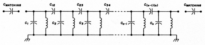
Fig. 1. General form of filter, showing matching capacitors and their placement.
The filters we're describing here are narrowband, capacitively-coupled designs (see fig. 1; note that the program prints out the capacitor values using these designators, so keep this figure in mind for future reference.) By narrowband, I'm specifically referring to the results of the following, well-known relationship.(1)(2)(3)
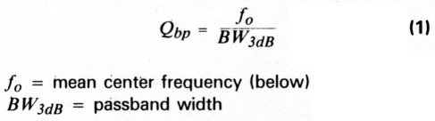
For these filters, Qbp must be ≥ 10. For Qbp < 10 other design techniques are better. References 1 and 2 are recommended for coverage of this sort of design, based on lowpass filters, and for converting them to bandpass.
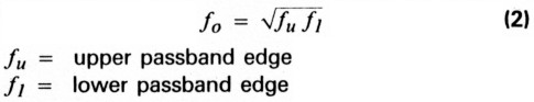
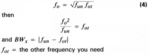
Like most bandpass filters, these filters have a geometric symmetry about the center frequency:
Because of this, the response of the attenuation versus frequency of these filters does not follow the arithmetical symmetry one might expect. Attenuation increases more rapidly on the low side of the passband.
Also, like most BPFs, these filters have passband versus stopband characteristics that are inevitably a compromise between passband ripple and attenuation at some out-of-band frequency. The optimally flat Butterworth (no-ripple) designs will have the poorest attenuation out-of-band. The Chebychevs, with varying amounts of ripple, will give more attenuation at the same out-of-band frequency, with the highest ripple designs giving the largest amount of attenuation. This attenuation also carries the price of being the most difficult of the filter types to build with real-world components.
Choosing the right filter for a job, then, becomes an exercise in compromise. In the front end of a receiver, for example, the ripple of the Chebychev might mean stations not copied (DX not worked). You might put up with a little less rejection of an out-ofband signal to hear those. Later on in the rig, a little gain can frequently be spared - perhaps the Chebychev should go there. One of the advantages of the program is that it allows you to compare designs before you plug in your soldering iron.
Using the program
To design a filter with this program, you need to know a few things: first, the center frequency (fo) and passband width. Both of these are entered in MHz. Next you need to know the required passband characteristics (i.e., Butterworth or 0.01 dB, 0.1, 0.5, or 1.0 dB ripple Chebychev), what inductor you plan to use, and how much attenuation is required at some frequency ratio.
This last one may be unfamiliar to you. This frequency ratio is expressed as:

where BWx is the bandwidth at some attenuation x, and BW, is the (3dB) passband width, as defined before. Often, you won't know BWx directly, but will know that there is some undesired frequency (fun), such as a broadcaster, or mixing product that you want to attenuate. You can solve for BWx by using the geometric symmetry of the filter, as follows:
You then divide this number by the bandwidth to get the ratio, f/fc, that the progam queries for. It is entered as a single number (i.e., 3 or 4.237) rather than as a ratio.
The filter that results will inevitably have some characteristic impedance that will never be the one you're looking for - per Murphy. To overcome this, a simple matching capacitor can be calculated for you by the program. It can match either end to another impedance, and does this by making the end sections a capacitive divider, with one capacitor in series with the input and output. It will recalculate the changed capacitor in the body of the filter for you. The only hazard here is that a large change in impedance may make one of the capacitors go negative in value. If this happens, you can redesign the filter with a bigger inductor, or else use another matching method of your own.
Sample filter
To illustrate the process, here's a filter that I needed for a 2-meter transverter. The bandwidth at 50 dB down was determined by a local NOAA Weatheradio signal at 162.55 MHz that I wanted to knock down as much as possible. The 3 dB bandwidth of the filter was determined by a need to cover all 4 MHz of 2 meters in the peak of the passband. My inputs to the computer are the requirements that I have for the filter:
- Type of filter: 0.5 dB ripple Chebychev
- Frequency Ratio f/fc: 4.13
- Desired Attenuation at f/fc: 50dB
At this point, the computer responds that an N = 4 (4 pole) filter will provide 61.08 dB (at km) and then asks for the center frequency (145), bandwidth (8), and the coil used (0.068 µH) It then calculates its responses. Its outputs are:
Coupling Capacitors:
C12 = .6334 pF
C23 = .5327 pF
C34 = .6334 pF
Resonating Capacitors:
C1 = 17.08 pF
C2 = 16.55 pF
C3 = 16.55 pF
C4 = 17.08 pF
It concludes by telling me that the characteristic impedance of the filter is 2050 ohms and asks me if I want to match to another. I request 50 ohms, both ends, add 3.47 pF to the end sections and change the end resonators, C1 and C4, to 13.613 pF (17.08-3.47).
Although this filter was touchy to align, it was built and aligned using sophisticated equipment, then measured on a Hewlett Packard Network Analyzer. The graphs of attenuation versus frequency for it are in fig. 3 along with its schematic fig. 2.
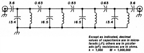
Fig. 2. The two meter filter uses 68nH, Coilcraft T-113 11/2 turn coils.
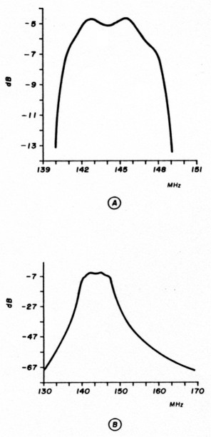
Fig. 3(A) 2-meter BP filter fine response; (B) 2-meter BP filter response shows stopband attenuation.
Building the filters
Of course all this is pretty meaningless without working filters that fit your needs - and the program, like all mathematical models, is perfectly capable of generating answers that solve its equations, but are completely absurd in the real world ... all of which requires the introduction of some sound ideas for building these filters.
To begin with, filters using conventional discrete coils and caps get progressively harder to build and align as frequency increases. The Amateur with the typical test equipment described below and good components and assembly techniques should have no trouble getting these filters to work up through 75 to 100 MHz. Those with high-quality equipment or access to it can expect to go to beyond 2 meters. Above 200 MHz, filter construction and alignment without large amounts of equipment demands other techniques, which will not be discussed here.
When it comes to components, the rule is to get the highest Q that you can obtain. Low Q causes losses in the filter, evidenced by higher insertion loss and changes in the passband shape. Capacitors are rarely a problem because they tend to have much higher Qs than coils. In an inductor:

where R is the ohmic resistance of the wire and XL is the inductive reactance. From this definition, it follows that you should use the largest practical size wire you can. Q is also affected by coil diameter, winding pitch, and core or support material. Adding a core always degrades Q as does shielding a coil.
The tradeoff here is that airwound, large diameter coils are fine at VHF, but too large at HF. Thankfully, iron powder and ferrite toroids provide increased inductance, virtually perfect shielding, and reasonable Qs from MF to the low VHF region. Amidon Associates provides data that allows you to predict Q and the number of turns to wind a given coil, on request.
While Q may not be a major concern with capacitors, stray reactances are. At RF, they contain enough stray inductance to present themselves as something far from a perfect capacitor. For example, a 0.001 µF ceramic disk capacitor with 1/4 inch leads appears as a series-resonant circuit (0 ohms) at 55 MHz, while a 0.01 is self-resonant at 15 MHz.(4) For this reason, it is imperative to keep leads as short as possible.
As for the type of capacitor to use, ultraminiature dipped ceramics are best at and above 6 meters, although their typical 50 VDC breakdown is low for transmitters. Through the HF spectrum, silver micas are an acceptable substitute. SMs have a higher stray inductance, but it's rarely a problem. They're available in higher voltage ratings, too.
Inductors also show stray reactance - in this case, capacitance between adjacent turns. This has the effect of making the inductor appear smaller than it is, and is especially noticeable as frequency increases.
One last word on component Q. The filter type chosen imposes some constraints on the minimum Q you can live with. Table 1, derived from reference 2, presents the approximate minimum Q for a lowpass filter of the given type and order. For bandpass filters, this must be multiplied by the Qbp, derived previously. From this, you can see how high-order Chebychevs would be difficult to realize, based on component Q alone.
| Type of Filter | Minimum Component Q | ||||||
|---|---|---|---|---|---|---|---|
| n= | 2 | 3 | 4 | 5 | 6 | 7 | 8 |
| Butterworth | 2 | 2 | 3 | 3 | 4 | 4 | 5 |
| 0.10 dB Chebychev | 2 | 3 | 5 | 7 | 10 | 14 | 17 |
| 0.50 dB Chebychev | 3 | 4 | 7 | 10 | 14 | 20 | 30 |
| 1.0 dB Chebychev | 3 | 5 | 8 | 12 | 17 | 26 | 35 |
| This table gives an approximate minimum component Q for use in a /owpass filter of the given order. For a bandpass filter, this value must be multiplied by the passband Q, Qbp. | |||||||
Component layout requires some thought. While an etched PC board is not necessary, at least through 6 meters, some readers may want to etch one anyway. The optimum layout is linear, with the components appearing as they are drawn on the schematic. If you must "bend" this line to fit into a space, try to keep input away from output and break grounds between them. A U-shaped layout isn't asking for trouble-it's begging.
Figure 4 is a "universal" four-pole filter prototyping board I've used from 1 to 200 MHz. It's etched on double-sided G-10, with the back solid groundplane. Components are soldered directly to the lands or the lands are jumpered out with copper foil for smaller numbers of sections. Top and bottom groundplanes are jumpered together by wires.
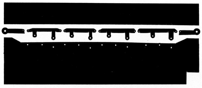
Fig. 4. Full size version of the "universal" 4 section filter card.
If you choose not to etch a board, or can't etch a board, take heart. Many prototypes in engineering labs are built in a style called "dead bug"; components going to ground are soldered to a piece of unetched PC material and those not grounded are supported by their leads going to those that are, or to each other. The only precautions necessary are to keep ground connections as short as possible and to not lay unshielded coils with their axes parallel to each other, or with turns touching. Toroids can be placed in any orientation to each other and can touch ground without trouble. As in etched boards, the best layout is a straight line.
Alignment
It should be obvious that the only differences between, say, a 1.0 dB Chebychev and a Butterworth of the same order are small component value differences. Knowing the value of the components is the most important step in getting the filter working.
There are many ways for measuring component values; a bridge can give quite accurate results, and commercial or homebrew capacitance meters abound. Lacking one of the above, a grid dip meter will do nicely. All you need are some capacitors and coils that will serve as your standards (known values). Using these, an unknown coil or cap can be measured by establishing it in a resonant circuit and measuring the frequency. The ARRL Handbook, at least up through the 1982 edition, included a chart for determining LC values using standards of 100 pF and 5µH, although you can use any standard you choose.' A frequency on the order of 10 MHz is fine for checking capacitors.
You'll find that the values the program prints out for capacitors are generally not standard and will have to be made up by paralleling one or two with a trimmer. Use the grid dipper to set the value. Likewise, coil values will not work out to an exact number of turns (e.g., 9.39 turns). What you'll have to do, if you're not using a variable coil, is wind the nearest whole number of turns and adjust the coil manually. This is done by setting the grid dip meter to the proper frequency and either squeezing together or spreading apart turns until the value is correct. Fix the turns in place with coil dope. Keep your hands clear while measuring!
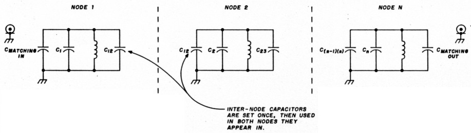
Fig. 5. Breaking up a filter into nodes for alignment.
Now that the parts are all the correct value, assemble the filter's nodes by shorting all of the caps around an inductor to ground (see fig. 5). All of the resulting sections are then tuned to the geometric center frequency, fo of the filter. Tune only one adjustment per node! If the parts are properly measured, this should be a very small "tweak"; none may be required below 50 MHz. Connect the filter into its final configuration.
Once the components and sections are tested and assembled, it's best to verify that the filter you have is the one you really wanted (see test setup in fig. 6). The signal source can be a cheap generator, either purchased or home-brewed, that puts out several milliwatts of RF. If the RF voltmeter can't read frequency, use a counter. A sweep generator and receiver make an excellent combination, although a sweeper makes some means of accurately measuring the output frequency critical.
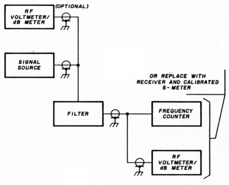
Fig. 6. Alignment verification set-up.
If two voltmeters are available, use one to keep the output from the source at the same level. If only one is available, set the source to some level and then sweep it across the filter's passband (still without the filter in line) while recording its level variation for a baseline. Then put the filter in line and sweep the generator across its range, say from the expected 3 dB points, or slightly beyond, while recording levels through the filter. A power meter permits immediate comparison of dB levels; a voltmeter requires a few minutes with a calculator. Once the readings are in dB, plot them versus frequency and see if you get what you expected. Without exceptional shielding in the generator and a more sophisticated detector, it won't be possible to determine stopband response. It's generally valid to assume that if your passband is within your expected limits, the stopband will be also.
If the transmission characteristics of your filter are not as desired, it may be necessary to try to tweak it in. No amount of advice can help here, however, so make sure you've performed all the preliminary steps properly before you start ripping it apart. Many of these filters - especially those built below 30 MHz - work perfectly the first time. Keep track of what you've done, and recheck it often. If worse comes to worst, retune all nodes and start over again. (If it's any consolation, it does get easier with practice.)
If possible, build some practice filters in the HF range to familiarize yourself with the program and alignment methods. Once you've done that, you should have no problems.
Fig. 7. Narrow-band filter CAD program listing.
1 REM LC BANDPASS FILTER DESIGN FOR NARROW BAND FILTERS
3 REM PROGRAMMED BY BOB LOMBARDI WB4EHS
100 PRINT CHR$(147)
105 Q=0:DIM K(7),C(8)
110 PRINT:PRINT:PRINT
120 PRINT "BANDPASS FILTER DESIGN PRO6RAM":PRINT:PRINT
122 PRINT "THIS PROGRAM COMPUTES VALUES FOR"
123 PRINT "PARALLEL RESONANT, CAPACITIVELY"
124 PRINT "COUPLED BANDPASS FILTERS":PRINT "THAT ARE (RVON)NARROW BAND(RVOF) -(Q>10)"
125 PRINT "ENTER THE NUMBER OF THE DESIRED"
126 PRINT "ROUTINE":PRINT:PRINT
130 PRINT "1 FOR BUTTERWORTH":PRINT
131 FRINT "2 FOR 0.01 DB CHEBYCHEV":PRINT
132 PRINT "3 FOR 0.1 DB CHEBYCHEV":PRINT
133 PRINT "4 FOR 0.5 DB CHEBYCHEV":PRINT
134 PRINT "S FOR 1.0 DB CHEBYCHEV":PRINT
145 INPUT O:IF O<0 AND O>5 THEN GOTO 135
146 ON O GOTO 1000,1100,1200,1300,1400

1000 REM BUTTERWORTH SECTION
1010 GOSUB 4000
1015 IF N=2 THEN Q=1.414:K(1)=0.707
1020 IF N=3 THEN Q=1.000:K(1)=0.707:K(2)=K(1)
1025 IF N=4 THEN Q=0.765:K(1)=0.841:K(2)=0.541:K(3)=K(l)
1030 IF N=5 THEN Q=0.618:K(1)=1.000:K(2)=0.556:K(3)=K(2):K(4)=K(1)
1035 IF N=6 THEN Q=0.518:K(1)=1.169:K(2)=0.605:K(3)=0.518:K(4)=K(2):K(5)=K(1)
1040 IF N=7 THEN Q=0.445:K(1)=1.342:K(2)=0.667:K(3)=0.527:K(4)=K(3)
1042 IF N=7 THEN K(5)=K(2):K(6)=K(1)
1045 IF N=8 THEN Q=0.390:K(1)=1.519:K(2)=0.736:K(3)=0.554:K(4)=0.510
1047 IF N=8 THEN K(5)=K(3):K(6)=K(2):K(7)=K(1)
1060 GOTO 2500

1100 REM 0.01 DB CHEBYCHEV SECTION
1110 R=.01:GOSUB 4500
1115 IF N=2 THEN Q=1.483:K(1)=0.708
1120 IF N=3 THEN Q=1.181:K(1)=0.682:K(2)=K(1)
1125 IF N=4 THEN Q=1.046:K(1)=0.737:K(2)=0.541:K(3)=K(1)
1130 IF N=5 THEN Q=0.977:K(1)=0.780:K(2)=0.540:K(3)=K(2):K(4)=K(1)
1135 IF N=6 THEN Q=0.937:K(1)=0.809:K(2)=0.550:K(3)=0.518:K(4)=K(2):K(5)=K(1)
1140 IF N=7 TEEN Q=0.913:K(1)=0.829:K(2)=0.560:K(3)=0.517:K(4)=K(3)
1142 IF N=7 THEN K(5)=K(2):K(6)=K(1)
1145 IF N=B THEN Q=0.997:K(1)=0.843:K(2)=0.567:K(3)=0.520:K(4)=0.510
1147 IF N=8 THEN K(5)=K(3):K(6)=K(2):K(7)=K(1)
1160 GOTO 2500

1200 REM 0,1 DB CHEBYCHEV SECTION
1210 R=0.1:GOSUB 4500
1215 IF N=2 THEN Q=1.638:K(1)=0.711
1220 IF N=3 THEN Q=1.433:K(1)=0.662:K(2)=K(1)
1225 IF N=4 THEN Q=1.345:K(1)=0.685:K(2)=0.542:K(3)=K(1)
1230 IF N=5 THEN Q=1.301:K(1)=0.703:K(2)=0.536:K(3)=K(2):K(4)=K(1)
1235 IF N=6 THEN Q=1.277:K(1)=0.715:K(2)=0.539:K(3)=0.518:K(4)=K(2):K(5)=K(1)
1240 IF N=7 THEN Q=1.262:K(1)=0.722:K121=0,542:K(3)=0.516:K(4)=K(3)
1242 IF N=7 THEN K(5)=K(2):K(6)=K(1)
1245 IF N=8 THEN Q=1.251:K(1)=0.728:K(2)=0.545:K(3)=0.516:K(4)=0.510
1247 IF N=8 THEN K(5)=K(3):K(6)=K(2):K(7)=K(1)
1260 GOTO 2500

1300 REM 0.50 DB CHEBYCHEV SECTION
1310 R=0.5:GOSUB 4500
1315 IF N=2 THEN Q=1.950:K(1)=0.123
1320 IF N=3 THEN Q=1.864:K(1)=0.647:K(2)=K(1)
1325 IF N=4 THEN Q=1.826:K(1)=0.648:K(2)=0.545:K13)=K(1)
1330 IF N=5 THEN Q=1.807:K(1)=0.652:K(2)=0.534:K(3)=K(2):K(4)=K(1)
1335 IF N=6 THEN Q=1.796:K(1)=0.655:K(2)=0.533:K(3)=0.519:K(4)=K(2):K(5)=K(1)
1340 IF N=7 THEN Q=1.790:K(1)=0.657:K(2)=0.533:K(3)=0.516:K(4)=K(3)
1342 IF N=7 THEN K(5)=K(2):K(6)=K(1)
1345 IF N=8 THEN Q=1.785:K(1)=0.658:K(2)=0.533:K(3)=0.515:K(4)=0.511
1347 IF N=8 THEN K(5)=K(3):K(6)=K(2):K(7)=K(1)
1360 GOTO 2500

1400 REM 1.0 DB CHEBYCHEV SECTION
1410 R=1.0:GOSUB 4500
1415 IF N=2 THEN Q=2.210:K(1)=0.739
1420 IF N=3 THEN Q=2.210:K(1)=0.645:K(2)=K(1)
1425 IF N=4 THEN Q=2.210:K(1)=0.638:K(2)=0.546:K(3)=K(1)
1430 IF N=5 THEN Q=2.210:K(1)=0.633:K(2)=0.535:K(3)=K(2):K(4)=K(1)
1435 IF N=6 THEN Q=2.250:K(1)=0.631:K(2)=0.531:K(3)=0.510:K(4)=K(2):K(5)=K(l
1440 IF N=7 THEN Q=2.250:K(1)=0.631:K(2)=0.530:K(3)=0.517:K(4)=K(3)
1442 IF N=7 THEN K(5)=K(2):K(6)=K(1)
1450 IF N=>8 THEN PRINT "CAN'T DO 8 POLE 1 DB CHEBUCHEV. CALCULATING 7 POLE."
1455 IF N=8 THEN N=7:GOTO 1440
1460 GOTO 2500

2500 REM CALCULATION AND DISPLAY ROUTINE
2510 PRINT "WHAT IS THE DESIRED CENTER"
2511 INPUT "FREQUENCY (IN MHZ)";F0
2515 F0=F0*1E6
2520 INPUT "WHAT IS THE 3 DB BM (IN MHZ)";BW:BW=BW*1E6
2530 INPUT "WHAT IS THE INDUCTOR (IN UH)";L:L=L*1E-6
2540 W=2*π*f0
2550 QB=F0/BW
2560 QC=QB*Q
2570 FOR I=1 TO N-1
2575 K(I)=K(I)/QB
2580 NEXT I
2590 CR=1/((W*W)*L)
2600 RE=W*L*QD
2610 FOR I=1 TO N-1
2670 K(I)=K(I)*CR
2680 NEXT I
2690 ON N-1 GOSUB 2700,2720,2740,2760,2780,2800,2820
2695 GOTO 2900

2700 C(1)=CR-K(1):C(2)=C(1):RETURN
2720 C(1)=CR-K(1):C(2)=CR-K(1)-K(2):C(3)=C(1):RETURN
2740 C(1)=CR-K(1):C(2)=CR-K(1)-K(2):C(3)=CR-K(2)-K(3):C(4)=C(1):RETURN
2760 C(1)=CR-K(1):C(2)=CR-K(1)-K(2):C(3)=CR-K(2)-K(3):C(4)=CR-K(3)-K(4)
2770 C(5)=C(1):RETURN
2780 C(1)=CR-K(1):C(2)=CR-K(1)-K(2):C(3)=CR-K(2)-K(3):C(4)=CR-K(3)-K(4)
2785 C(5)=CR-K(4)-K(5):C(6)=C(1):RETURN
2800 C(1)=CR-K(1):C(2)=CR-K(1)-K(2):C(3)=CR-K(2)-K(3):C(4)=CR-K(3)-K(4)
2805 C(5)=CR-K(4)-K(5):C(6)=CR-K(5)-K(6):C(7)=C(1):RETURN
2820 C(1)=CR-K(1):C(2)=CR-K(1)-K(2):C(3)=CR-K(2)-K(3):C(4)=CR-K(3)-K(4)
2825 C(5)=CR-K(4)-K(5):C(6)=CR-K(5)-K(6):C(7)=CR-K(6)-K(7):C(8)=C(1):RETURN

2900 PRINT:PRINT:PRINT
2910 PRINT "COUPLING CAPS ARE	(IN PF)"
2915 FOR I=1 TO N-1
2920 PRINT "C";I;I+1;": ";K(I)*1E12
2930 NEXT I
2935 PRINT
2940 PRINT "RESONATING CAPS ARE (IN PF)"
2945 FOR I=1 TO N
2950 PRINT "C";I;": ";C(I)*1E12
2960 NEXT I
2970 PRINT "THIS FILTER HAS A CHARACTERISTIC Z"
2975 PRINT "OF";RE;"OHMS.":PRINT
2980 INPUT "MATCH TO ANOTHER Z";A$:IF A$<>"Y" AND A$<>"N" THEN GOTO 2980
2985 IF A$="N" GOTO 3100
2990 INPUT "NEW SOURCE AND LOAD Z (50,50):";RS,RL
2992 PRINT
2995 TM=SQR(RE*RS-RS*RS):TN=SQR(RE*RL-RL^2)
3000 CY=1/(W*TM):CZ:1/(W*TN)
3005 PRINT "ADD";CY*1E12;" PF	TO THE SOURCE END"
3006 PRINT "AND ADD";CZ*1E12;" TO THE LOAD END."
3010 PRINT:PRINT "THEN CHANGE C(1) TO";(C(1)-CY)*1E12;" PF"
3020 PRINT "AND CHANGE C(";N;") TO "(C(N)-CZ)*1E12;" PF."
3100 PRINT:PRINT
3110 INPUT "ANOTHER FILTER (Y OR N)";A$
3115 IF A$<>"Y" AND A$<>"N" THEN 3110
3120 IF A$="Y" THEN 120
3200 END

4000 REM FILTER ORDER CALCULATION ROUTINE
4010 REM BUTTERWORTH SECTION
4020 PRINT "ENTER FREQUENCY RATIO F/FC AS A NUMBER, I.E. 3":INPUT WR
4025 INPUT "DESIRED ATTENUATION AT F/FC";AD
4030 FOR N=2 TO 8
4040 AC=10*(LOG(1+WR^(2*N)))/(LOG(10))
4050 IF AC=>AD GOTO 4070
4060 NEXT:GOTO 4100
4070 PRINT "N=";N;"AT A CALCULATED A=";AC;"DB":RETURN
4100 PRINT "THE REQUIRED ATTENUATION IS OUT OF RANGE FOR A BUTTERWORTH FILTER"
4110 PRINT "OF UP TO 8 POLES."
4120 PRINT "A LOW RIPPLE CHEBYCHEV MAY WORK.":GOTO 130
4130 STOP

4500 REM CHEBYCHEV CALCULATION ROUTINE
4510 DEF FNCS(X)=0.5*(EXP(X)+EXP(-X))
4520 DEF FNASH(X)=LOG(X+SQR(X^2+1))
4530 INPUT "ENTER THE FREQUENCY RATIO F/FC AS A NUMBER I.E. 3";WR
4540 INPUT "DESIRED ATTENUATION AT F/FC";AD
4560 EP=SQR(10^(R/10)-1)
4565 N=2
4570 B=(FN ASH(1/EP))/N
4580 WC=(FN CS(B))*WR
4590 CN=(2*WC^2-1)
4600 AC=10*LOG(1+EP^2*CN^2)/LOG(10)
4610 IF AC=>AD THEN PRINT "N=";N;" AT A CALCULATED A=";AC;"DB":RETURN
4620 N=3
4630 B=(FN ASH(1/EP))/N
4640 WC=(FN CS(B))*WR
4650 CN=(4*WC^3-3*WC)
4660 AC=10*LOG(1+EP^2*CN^2)/LOG(10)
4670 IF AC=>AD THEN PRINT "N=";N;" AT A CALCULATED A=";AC;"DB":RETURN
4700 N=4
4710 B=(FN ASH(1/EP))/N
4720 WC=(FN CS(B))*WR
4730 CH=(8*WC^4-8*WC^2+1)
4740 AC=10*LOG(1+EP^2*CN^2)/LOG(10)
4750 IF AC=>AD THEN PRINT "N=";N;" AT A CALCULATED A=";AC;"DB":RETURN
4800 N=5
4810 B=(FN ASH(1/EP))/N
4820 WC=(FN CS(B))*WR
4830 CN=(16*WC^5-20*WC^3+5*WC)
4840 AC=10*LOG(1+EP^2*CN^2)/LOG(10)
4850 IF AC=>AD THEN PRINT "N=";N;" AT A CALCULATED A=";AC;"DB":RETURN
4900 N=6
4910 B=(FN ASH(1/EP))/N
4920 WC=(FN CS(B))*WR
4930 CN=(32*WC^6-48*WC^4+18*WC^2-1)
4940 AC=10*LOG(1+EP^2*CN^2)/LOG(10)
4950 IF AC=>AD THEN PRINT "N=";N;" AT A CALCULATED A=";AC;"DB":RETURN
5000 N=7
5010 B=(FN ASH(1/EP))/N
5020 WC=(FN CS(B))*WR
5030 CN=(64*WC^7-112*WC^5+56*WC^3-7*WC)
5040 AC=10*LOG(1+EP^2*CN^2)/LOG(10)
3050 IF AC=>AD THEN PRINT "N=";N;" AT A CALCULATED A=";AC;"DB":RETURN
5100 N=8
5110 B=(FN ASH(1/EP))/N
5120 WC=(FN CS(B))*WR
5130 CN=(128*WC^8-2561WC^6+160*WC^4-32*WC^2+1)
5140 AC=10*LOG(1+EP^2*CN^2)/LOG(10)
5150 IF AC=>AD THEN PRINT "N=";N;" AT A CALCULATED A=";AC;"DB":RETURN

5200 PRINT "THE DESIRED ATTENUATION IS NOT WITHIN	RANGE OF THIS PROGRAM."
5210 PRINT "FOR THE CHOSEN FILTER TYPE."
5220 PRINT "A HIGHER RIPPLE DESIGN MAY MEET YOUR RE-AUIREMENTS."
5230 GOTO 130
References
- Chris Bowick, RF Circuit Design, Howard W. Sams B Co., 1982, Chapters 2 and 3.
- Arthur B. Williams, Electronic Filter Design Handbook, McGraw-Hill, 1981, pages 2-8 through 5-24.
- Wes Hayward, W7ZOI, Introduction to Radio Frequency Design, Prentice-Hall, 1982, pages 90-101.
- The Radio Amateur's Handbook, American Radio Relay League, 1982, pages 16-21, 17-9.
WB4EHS, Bob Lombardi.