High dynamic range mixing with the Si8901
Extends intermod HF/VHF performance at lower drive
The dynamic range of a mixer is intimately related to how well its intermodulation products are suppressed, how well the mixer can handle high-level signals, and its overall noise figure. Whether a mixer offers conversion gain or loss is secondary to the benefits derived from a high dynamic range. In fact, conversion gain simply transfers the problems associated with dynamic range from the mixer to subsequent amplifier stages.
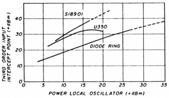
Fig. 1. Performance comparison of double-balanced mixers.
Until now, most mixers sporting a high dynamic range have required a correspondingly high local oscillator drive, as shown in the performance comparison in fig. 1. The popular diode-ring double-balanced mixer (DBM), shown in fig. 2, often requires the local oscillator power to exceed the signal compression level by at least 6 dB.
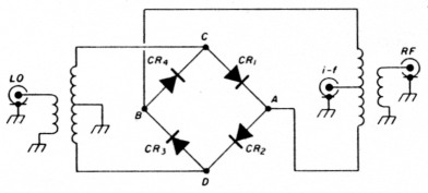
Fig. 2. Diode ring double-balanced mixer.
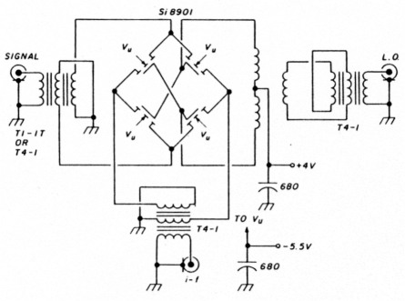
Fig. 3. Prototype commutation double-balanced mixer.
The Siliconix Si8901 DBM (fig. 3) is a monolithic quad-MOSFET ring demodulator especially suited for hf and low VHF operation where, operating as a commutation (switching) mixer, it is capable of two-tone, third-order input intercepts exceeding +37 dBm and a 2-dB signal overload compression and desensitization of +30 dBM - all at a local oscillator drive level of only + 17 dBm (50 mW)! An additional benefit of this low local oscillator drive results when, in combination with the traditionally high interport isolation afforded by DBM design, little re-radiated power exits the mixer through the signal port.
The Si8901 is available in the hermetic TO-99 package, suitable for full military applications, as well as in a surface-mount SO-14, which is useful for modern industrial and Amateur applications where high dynamic range is mandatory.
Theory of operation - conversion efficiency
Unlike the diode-ring mixer, the commutation mixer relies on the switching action of the quad-MOSFET elements to effect mixing action. Consequently, the Si8901 is, essentially, a pair of switches reversing the phase of the signal at a rate determined by the local oscillator frequency. Ideally, we would expect little noise. Since the MOSFET exhibits a finite on-resistance, the conversion efficiency is expressed as a loss. This loss results from two related factors: first, the rpslon) of the MOSFETs relative to both the signal and i-f impedances, and second, signal conversion to undesired frequencies.
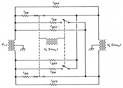
Fig. 4. Equivalent circuit of commutation mixer.
The effect of rDS(on) on both the signal and the i-f impedances (Rg and RL, respectively) may be derived from analysis of an equivalent circuit (fig. 4), assuming the local oscillator drive is an idealized square wave. The term 4/π2 is the power function of the Fourier series of an idealized square-wave excitation.
Conversion loss for an ideal mixer with the image and sum frequency (RF + LO) ports shorted may be expressed in terms of rDS(on), Rg, and RL as follows:
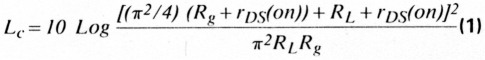
If we let rDS(on) = 0 and resistively-terminate the image and sum frequency ports the minimum attainable conversion loss reduces to
![]()
which computes tot Lc = -3.92 dB. In a practical sense we need to add 3.92 dB to the results of eqn. 1 or fig. 5 to obtain the true conversion loss.
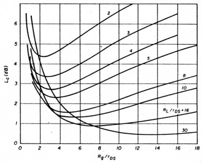
Fig. 5. Insertion Loss as a function of rDS, RL, and Rg
Equation 1 plotted for various ratios of Rg, RL, and rDS(on) (fig. 5) illustrates how seriously the on-resistance of the MOSFETs affects the conversion loss.
Intermodulation distortion
| Single-balanced | Double-balanced |
|---|---|
| fS | |
| 3fS | |
| 5fS | |
| f1 ± f2 | f1 ± f2 |
| f1 ± 3f2 | f1 ± 3f2 |
| f1 ± 5f2 | f1 ± 5f2 |
| 2f1 ± f2 | |
| 3f1 ± f2 | 3f1 ± f2 |
| 3f1 ± 3f2 | 3f1 ± 3f2 |
| 4f1 ± f2 | |
| 5f1 ± f2 | 5f1 ± f2 |
Unbalanced, single-balanced, and double-balanced mixers are distinguished by their ability to reject spurious frequency components selectively, as defined in table 1. In the majority of mixer applications, the most damaging intermodulation distortion products (IMD) are those attributed to odd order and, in particular, those identified as the third order (IMD3).
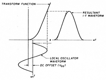
Fig. 6. Effect of sinusoidal local-oscillator waveform on i-f linearity.
Although the DBM outperforms the single-balanced mixer, a more serious source of intermodulation products results when the local oscillator excitation departs from the idealized square wave. This phenomenon is easily recognized by a careful examination of fig. 6, which shows the effect of sinusoidal local oscillator voltage on varying transfer characteristics. Since optimum IMD performance demands that the switches of a commutation mixer operate in a 50-percent duty cycle (i.e., fully on and fully off for equal times), some offset voltage is necessary.
Walker' has derived an expression showing the predicted improvement in the relative level of two-tone, third-order IMD as a function of the rise and fall times of the local oscillator waveform.

where:
Vc is the peak-to-peak local oscillator voltage
Vs is the peak signal voltage
tr is the rise and fall time of Vc
ωLO is 2πfLO where fLO is the local oscillator frequency.
Equation 3 shows that by lowering Rg (which, in turn, decreases the magnitude of Vs) IMD performance is improved. Likewise, increasing the local oscillator voltage, Vc improves IMD performance. Finally, if we can provide idealized square-wave excitation, we achieve the perfect mixer! Additionally, we see that low-side injection is more efficient than high-side injection.
Further justification for square-wave local oscillator drive is an additional fault of sinusoidal excitation. Whenever the exciting wave approaches zero crossing at half-period intervals, the FETs, in effect, lose their bias, and serious signal voltage overload results in severely degraded IMD performance. The effects of sinusoidal excitation on gate bias are easily seen in fig. 7.
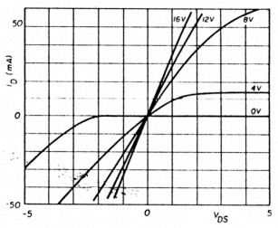
Fig. 7. First- and third-quadrant I-E characteristics showing effect of gate voltage leading to large-signal overload distortion.
Building the mixer
Based on the knowledge derived from eqn. 3, low source resistance, Rg, and high local oscillator excitation voltage, Vc, are ideal conditions for a mixer. The Si8901, operating as the mixer switch, offers a typical on-resistance of approximately 23 ohms when excited by a gate potential of 15 volts. Using the popular 4:1 i-f output transformer to a 50-ohm preamplifier, (RL/rDS(on) ≈ 8), fig. 5 suggests optimum conversion efficiency with an Rg of 92 ohms. This is contradicted in eqn. 3, which shows that optimum IMD performance results with the lowest possible Vs. This result is achieved by lowering Rg. It now becomes clear that a performance tradeoff may be necessary. Either we seek low conversion loss, and with it a low noise figure, or aim for the highest IMD performance. Fortunately, as we seek high performance, the dynamic range will improve since a mismatched signal port has less effect upon the signal-to-noise performance than a matched signal port has upon IMD.
Establishing the gate drive
Using the conventional broadband, transmission-line transformer characteristic of the diode-ring DBM requires massive local oscillator drive to effect the required gate voltage needed to satisfy eqn. 3. Earlier MOSFET commutation mixers required watts of local oscillator drive to achieve high dynamic range!(2)
One obvious means of obtaining a high gate voltage is to use a resonant gate drive. The voltage appearing across the resonant tank, and thus on the gates, may be calculated as
![]()
where:
P is the local oscillator power delivered to the resonant tank
Q is the loaded Q of the resonant tank
X is the reactance of the gate
Since the gate capacitance of the MOSFETs is voltage dependent, the reactance becomes dependent upon the impressed excitation voltage. To allow this condition would severely degrade the IMD performance of the mixer. However, this reactive dependence on excitation voltage can be minimized using a combination of gate and substrate biasing. As we saw in fig. 6, the offset gate bias helps to achieve the required 50-percent duty cycle for optimum IMD performance.
| power in (mW) | non-resonant gate voltage (V) | resonant gate voltage (V) |
|---|---|---|
| 10 | 0.20 | 5.4 |
| 20 | 0.29 | 7.7 |
| 30 | 0.33 | 9.4 |
| 60 | 0.44 | 13.3 |
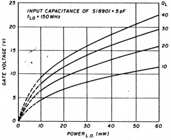
Fig. 8. Influence of loaded Q on gate voltage vs. local-oscillator power.
Table 2 and fig. 8 offer an interesting comparison between a resonant-gate drive with a loaded Q of 14 and conventional drive using a 50 ohm to 200 ohm (100-0-100) 4:1 transformer. The full impact of a high-voltage gate drive can be seen in fig. 9, which shows close agreement between the calculated (eqn. 3) and the measured IMD.
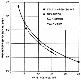
Fig. 9. Effect of gate voltage on IMD performance.
Designing the mixer
Achieving the low signal input impedance can be easily accomplished using the Mini-Circuits T1-1T (1:1) broadband transformer. Likewise, for the i-f output, the Mini-Circuits T4-1 (4:1) does an excellent job.
The principal effort is the resonant gate drive, which necessitates an accurate knowledge of the Si8901's total capacitive loading. The data sheet offers typically 4.4 pF. To ensure good interport isolation, symmetry is critical. If this resonant tank is driven from an asymmetrical local oscillator source (coax), an unbalancedto-balanced transformer ensures symmetry (see complete mixer schematic shown in fig. 3).
Performance of the Si8901 commutation mixer
The following tests were performed across the 2-to-30 MHz hf band.
- conversion efficiency (loss)
- two-tone, third-order intercept point
- compression level
- desensitization level
- noise figure
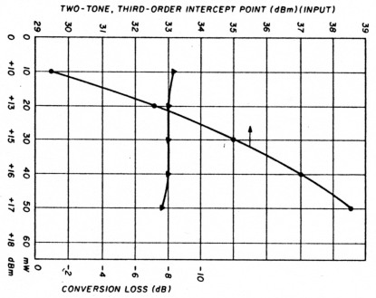
Fig. 10 Intercept point and conversion loss.
The conversion loss and input intercept point are plotted as a function of local oscillator drive power in fig. 10.
The 2-dB compression and desensitization levels appear to contradict what is normally expected based on the +17 dBm local oscillator drive until we are reminded that the mixer's performance is based on gate voltage, not gate drive expressed as power. Both were measured at +30 dBm. The single-sideband noise figure was 7.95 dBm.
If the design engineer follows the concepts suggested in this note, the Siliconix Si8901 will provide the highest dynamic range of any comparable mixer currently available. Achieving a high gate voltage using a resonant drive does not label the mixer as a narrow-band device. Tank tuning may be accomplished in a number of ways, such as electronic tuning using varactors. It is conceivable that the tank may be the output of an electronically tuned balanced local oscillator circuit.
References
- H.P. Walker, "Sources of Intermodulation in Diode-Ring Mixers," The Radio and Electronic Engineer, Vol. 46, No. 5, May 1967, p. 247-255.
- R.P. Rafuse, "Symmetric MOSFET Mixers of High Dynamic Range," Digest of Technical Papers, 1968 International Solid-State Circuits Conference, p. 122-123.
KB6QJ, Ed Oxner.