Decoding data signals
Algorithm improves teletype™ performance in noisy environment
Increasing numbers of Amateurs are involved in data communications. On VHF, many hams use fm transmitters to broadcast via Audio Frequency Shift Keying (AFSK). Direct FS K is the normal mode of transmission on hf.
In the absence of fm, hf data transmission is particularly sensitive to noise - especially at the higher data rates. Packet radio, even with its automatic error correction, is affected by high noise sensitivity. This results in frequent retransmission of packets, slowing the data transmission rate. Packet ensures the information will be correctly received eventually. I thought it was possible to do better and looked into ways to minimize this sensitivity.
Hardware fixes
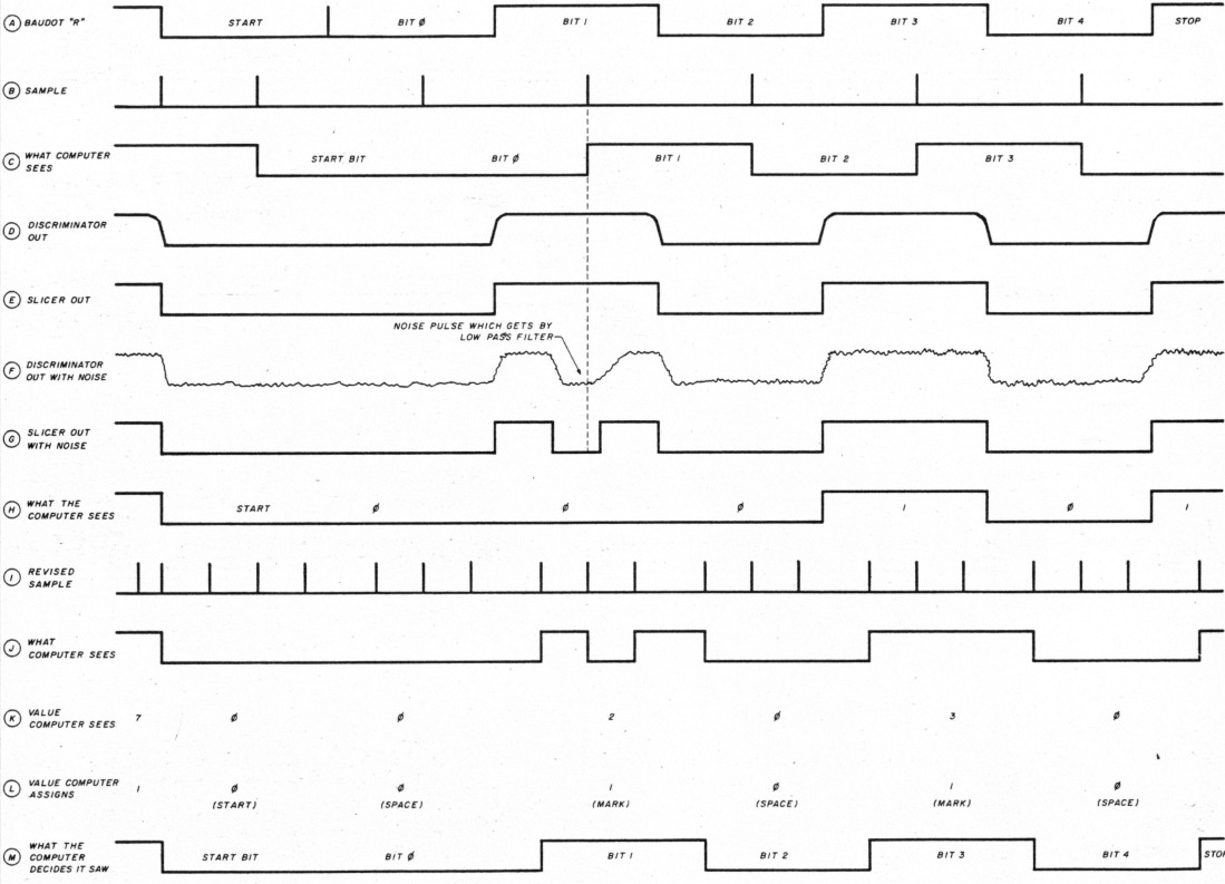
Fig 1 - Waveform rendition of the letter "R" at various system locations.
An obvious way to improve noise rejection is to modify the hardware used to convert audio signals into pulses for the computer or TTY. Line A of fig. 1 shows the pulses transmitted to send the letter "R" in Baudot. Figure 2 is a block diagram of a typical demodulator, similar to the ST-5 or the demodulator used in the PK-232. It consists of a limiter followed by a bandpass filter that removes all signals above and below the mark and space tones. A linear discriminator converts the frequency shift information to varying dc levels. The "slicer", a high-gain comparator, converts the discriminator output levels to discrete pulses which can be used to key a TTY or computer. The circuit is vulnerable to interference from spurious signals between the mark and space frequencies.
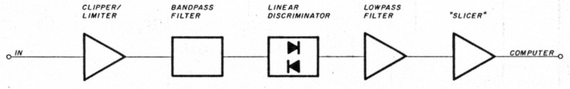
Fig 2 - Typical RTTY demodulator.
Figure 3 shows an improved demodulator. It uses separate filters to select the distinct mark and space frequencies, reducing the vulnerability to spurious signals and improving the signal to noise ratio. Other hardware improvements are possible but difficult, so I turned to improving the computer.
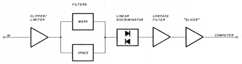
Fig 3 - Improved RTTY demodulator.
Software solutions
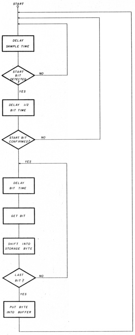
Fig 4 - Serial to parallel decoding algorithm.
The flow chart in fig. 4 shows how computer programs convert serial data to parallel information for storage and display. The input line is sampled at a rate that is a multiple of the bit rate. For this example, I've chosen a factor of 7. The computer samples the input for a start pulse. If one is present, the computer waits for one-half of the bit time and samples again. If the start bit is still there, the computer accepts this as a valid start pulse rather than noise. Delaying half a bit time puts the sample window near the center of each bit. The computer now delays a whole bit time and samples the input line for the first bit. After another full bit time delay, the computer gets the next bit. This continues until the last bit has been received and the entire character has been assembled. The character is now placed in a buffer to be stored, processed, or displayed. In fig. 1, line B shows the sample window. It is shown as a spike because it is so much shorter than the bit time (typically a few microseconds). Line C shows the data as the computer receives it - displaced by one-half bit time. The original pulse relationships and timing are maintained despite the delay. This sampling method resembles that used by hardware serial to parallel converters (ACIAs) like the 6551 and 6850.
Ina noise-free system, the pulses emerging from the demodulator are identical to the original. In a noisy environment, the demodulator's discriminator contains noise which can corrupt the slicer's output (even though it's low-pass filtered). Line G of fig. 1 shows the slicer output, and line H shows what the computer sees - an incorrect character which occurs because the computer looks at such a small window of the total bit time. A single noise pulse can corrupt the data, even though most of the bit is intact. Most Amateur systems waste time between samples; it is possible to use this time to make the computer smarter.
Figure 5 shows a flow chart for an improved algorithm. Initially, the computer takes seven samples per bit time, looking for a start pulse. When it detects a possible start bit, the computer waits two sample periods and takes another sample. (The delay prevents framing errors.) This pattern continues until three samples have been made. If two or three of the samples indicate that a start bit was present, a valid start is assumed. If not, the computer reverts to sampling each sample period in search of a start bit.
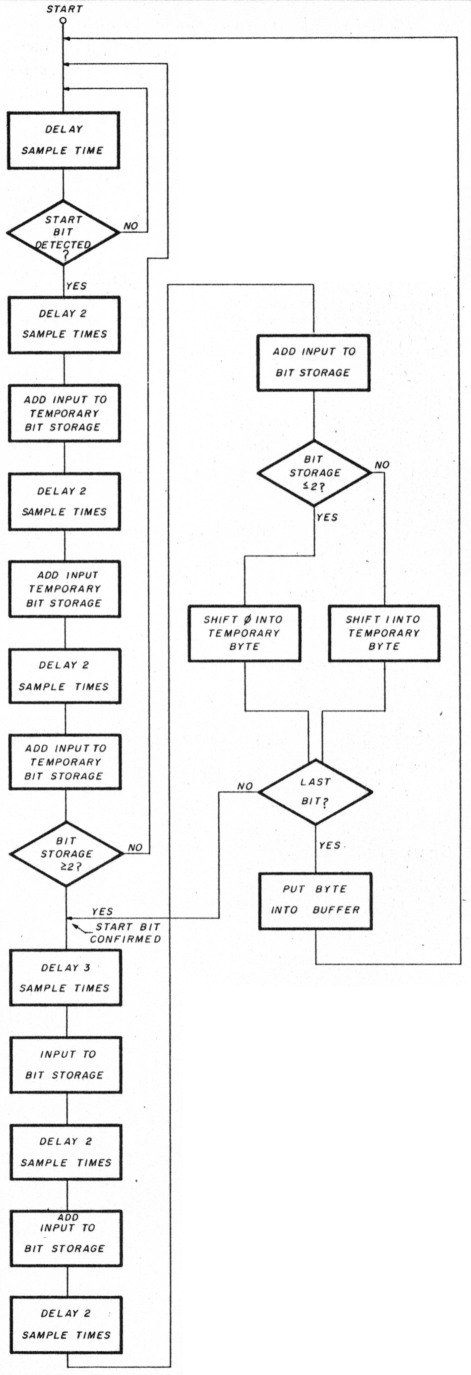
Fig 5 - Improved algorithm.
When a valid start bit is detected, the computer waits three sample periods and makes the first sample in the first bit. Three samples are taken per bit, with a delay of two periods between stored samples. After the samples for each bit have been collected, it is determined if the bit was a zero or a one. (I've chosen a simple majority of samples scheme; more sophisticated methods are possible.) This continues until all bits have been received and the character is stored in the buffer. Line I of fig.1 shows the revised sampling process; line J shows what the computer sees, given the noisy signal shown in lines F and G. Line K shows how the sample results are interpreted, and line L shows the results of the majority of samples. Line M shows the correctly reconstructed pulse train. Obviously, this process is not perfect. A long noise pulse which corrupts several samples within a bit can still corrupt the entire character.
This generic process can be enhanced in several ways. More samples per bit time yield greater noise immunity. The upper limit is determined by the amount of other processing your machine needs to do between samples.
You may wish to sample five times per bit at each sample period instead of every other sample period.
Although I've demonstrated the concept using Baudot code, the data can be simple ASCII or any other serial format. As mentioned earlier, using this process in a packet or AMTOR system can improve throughput by reducing the number of error-related retransmissions.
Implementation
How do you put this to use in your system? The timing involved is too fast and critical for interpreted languages like BASIC. I used assembly language for the 6809 microprocessor with 21 samples per bit. (See fig. 6.) A compiled language like C will probably work as well, depending on the speed of your machine and the efficiency of your compiler. While I don't have the test equipment to make quantitative comparisons, on-theair tests show that the "smart" algorithm is a noticeable improvement over a more conventional scheme.
Fig 6 - Assembly language decoding algorithm for the 6809 microprocessor.
00100 ###########################################
00115 # SMART DEMODULATION ALGORITHM            #
00125 # THIS INTERRUPT ROUTINE IS DESIGNED      #
00135 # TO BE CALLED 21 TIMES PER BIT TIME      #
00145 # IT ASSEMBLES THE RECEIVED CHARACTER     #
00155 # AND STORES IT IN A BUFFER. BETWEEN      #
00165 # INTERRRUPTS THE MAIN PROGRAM CAN GET    #
00175 # THE CHARACTER AND DISPLAY IT. NOTE      #
00185 # THAT A BADDOT CHARACTER WILL BE         #
00195 # AS SENT, AND LEFT JUSTIFIED. THE MAN    #
00205 # PROGRAM MUST SHIFT THE CHARACTER INTO   #
00206 # THE LSB'S AND TRANSLATE TO ASCII FOR    #
00207 # STORAGE. (USE A TRANSLATION TABLE.)     #
00208 # COPYRIGHT 1987 BY JAMES A. SANFORD      #
00209 # WB4GCS/NNNOHDF                          #
00210 ###########################################
00220
00221 #WRITTEN IN 6809 ASSEMBLY LANGUAGE        #
00222 #INCOMING DATA RECEIVED AT SFF22, BIT 0   #
00250
00300 SZIN    EQU    $100
00310 SZOUT   EOU    $100
00360 BITS    RMB    1       BITS/WORD INCLUDING STARTSTOP
00380 RXCTR   RMB    1       BITS RCVD
00381 RBTSTR  RMB    1       STORAGE FOR ACCUMULATED BITS
00386 RHITS   RMB    1       STORAGE FOR NUMBER OF SAMPLES
00390 TXCKS   RMB    1       TIMES PULSE CHECKED
00400 RXCKS   RMB    1       TIMES PULSE CHECKED
00450 XTMP    RMB    1       TEMP STORAGE FOR TX CHAR
00460 RIMP    RMB    1       TEMP STORAGE FOR RX CHAR
00470
00480 ONXTI   RMB    2       PTR FOR NEXT CHAR INTO OUT BUFFER
00490 ONXTO   RMB    2       PTR FOR NEXT CHAR FROM BUFFER TO SEND
00500 INXTI   RMB    2       PTR FOR NEXT RCVD CHAR TO BE STORED
00510 INXTO   RMB    2       PTR FOR NEXT RCVD CHAR TO BE SHOWN
00550
00551
02600         TITLE  INTERRUPT HANDLER
02610 FIRQ    PSHS   B
03215 RFIRQ   LDB    RXCTR   SEE IF RECEIVING ALREADY
03220         BEG    RFNDST  NO GO LOOK FOR START BIT
03225         DEC    RXCKS   YES
03230         BEG    RUPDT
03235         LBRA   RIDON
03240
03245 RFNDST
03250         TST    RXCKS   IF 0, LOOKING FOR FIRST HINT OF START BIT
03255         BEG    FSTRT1
03260         DEC    RXCKS   ALREADY INTO IT; CHECK DELAY
03265         LBNE   RIDON   STILL WRITING
03270         LOB    $FF22   GET IT
03275         RORB
03280         BCS    RSTRT2
03285         INC    RBTSTR  UPDATE COUNTER
03290 RSTRT2  INC    RHITS   UPDATE NUMBER OF SAMPLES
03295         LDB    RHITS
03300         CMPB   #6
03305         BEG    RSTRT3
03310         LDB    12      NOT DONE, DELAY
03315         STB    RXCKS
03320         LBRA   RIDON
03325
03330 RSTRT3  LDB    RBTSTR
03335         CMPB   #4
03340         BLO    NOSTRT  NOT GOOD ENOUGH, START OVER
03345         LOB    #11     DELAY INTO NEXT FRAME
03350         STB    RXCKS
03355         LDB    BITS    SETUP TO GET DATA
03360         SUBB   #2      ADJUST, ALREADY HAVE START BIT
03365         STB    RXCTR
03370 RSTRT4  CLR    RHITS
03375         CLR    RBTSTR
03380         LBRA   RIDON
03385 NOSTRT  CLR    RXCKS
03390         BRA    RSTRT4
03395
03400 FSTRT1  LDB    $FF22
03405         RORB
03410         BCS    RIDON   NO START BIT EXIT
03415         LDB    #5      START BIT, DELAY
03416         STB    RXCKS
03417         BRA    RIDON
03420
03435 RUPDT   LDB    $FF22   GET DATA BIT
03440         RORB           SHIFT INTO CARRY
03445         BCC    RUPD1   DATA BITS A 0
03450         INC    RBTSTR  DATA BITS A 1, COUNT IT
03455
03460 RUPD1   LDB    #2
03465         STB    RXCKS   WAIT 2 SAMPL TIMES, START AGAIN
03467         INC    RHITS
03470         LDB    RHITS
03475         CMPB   #6      6 SAMPLES YET?
03480         ENE    RIDON   NO, DONE FOR NOW
03485         LDB    RBTSTR  WE HAVE 6 SAMPLES, HOW MANY WERE 1?
03490 RUPD2   CMPB   #4      IF < 4, THE CMP WILL CAUSE A
03495 #                      BORROW AND SET THE C BIT IN THE
03500 #                      CONDITION CODE REGISTER. WE'LL CALL
03505 #                      THIS BIT A ZERO.
03510         EXG    B,CC    IF > 4 ONES C WILL BE CLEAR, AND
03515 #                      WE'LL CALL THE BIT A 1
03520         EORB   #1      THE C BIT IS THE COMPLEMENT OF THE
03525 #                      REAL DATA SO TOGGLE THAT BIT
03530         EXG    B,CC    NOW RESTORE REGISTERS
03535         LDB    RTMP    GET THE BITS WE'VE ALREADY GOT
03540         RORB           ROTATE NEW DATA BIT INTO TEMP
03545         STB    RTMP    STORAGE
03550         LDB    #11     SETUP TODELAY 3 SAMPLES FOR NEXT BIT
03555         STB    RXCKS
03560         CLR    RHITS
03565         CLR    RBTSTR  INITIALIZE COUNTERS
03566         DEC    RXCTR
03570         BNE    RIDON   WE'RE DONE.
03650 RSTOR   PSHS   X
03660         LDX    INXTI   GET PTR
03670         LDB    RTMP
03680         CMPB   #$FF    CK, FOR ERRONEOUS END OF DATA FLAG
03690         BNE    RSTORI  WHICH MAY HAVE BEEN CAUSED BY NOISE
03700         LDB    #$FE    IF SO CHANGE TO $FE WHICH WON'T AFFECT
03710 #                      BAUDOT, AND WILL HAVE MINIMAL EFFECT
03720 #                      ON ASCII TEXT. (NEVER INTENDED TO XFER
03730 #                      BINARY FILES IN ASCII)
03740 RSTOR1  STB    X+      TOBUFFER
03750         CMPX   #INBUF+SZIN
03760         BNE    RBFUP
03770         LDX    #INBUF
03780
03790 RBFLIP  STX    INXTI   UPDATE BUF PTR
03800         CMPX   INXTO   THIS EXTRA ATTENTION TO BUFFER
03810         BNE    RBFUPI  MANAGEMENT IS NECESSARY TO
03820         LEAX   1,X     PREVENT NOISE INDUCED ERRATIC
03830         CMPX   MINBUF+SZIN
03840         BLO    RBFUP2  BEHAVIOR DURING DISK OPERATIONS
03850         LDX    #INBUF  OR BUFFER TRANSMISSION.
03860 RBFIP2  STX    INXTO
03870 RBFUP1  PULS   X
03880
03890 RIDON   PULS   B
03900         RTI
I'm interested in any results you get using this method, suggestions you may have for improving the technique, or other ways you've found to improve data copy. NOTE: A complete working program for the Radio Shack® TRS80 color computer 3 is available from the author for $ 15.00. It features split screen, auto capture buffer ISELCALL), and several Baudot speeds as well as 300 baud ASCII.
WB4GCS, James A. Sanford.