An improved agc circuit
Add this circuit to your Kenwood TS-940S or TS-930S for DATA/RTTY reception.
Automatic gain control (AGC) circuits are used in receivers to adjust the gain of RF and IF amplifiers automatically. This prevents overdriving of the amplifier stages and maintains audio that's nearly constant with the varying strength of the input signal.
When propagation conditions are good, interference from atmospheric noise is minimal, and adjacent channel chatter from other signals is low, any AGC circuitry will provide satisfactory results for most modes of reception. However, when fading is prevalent, or atmospheric noise increases due to summer electrical storms and adjacent channel chatter builds up, it's important to improve the design of the AGC system. While even a well-designed AGC system won't take the place of an effective noise blanker, it will supplement the blanker and let you receive information you'd lose in the presence of adverse conditions.
I realize that many of you may question the efficacy of changing an AGC system like the one in the TS-940S. Since the system doesn't generate any clicks or pops and works satisfactorily for SSB, AM, and CW, consider that chang.ng it runs contrary to the old adage "If it ain't broke don't fix it." My question to you is: does it work well enough for data communications - RTTY, AMTOR, and packet? After a year or more of careful record keeping and diagnosis, I concluded the system wasn't effective enough. I found that nearly every case of an RTTY "hit" or error in the copy had occurred on days when there was static from electrical storms. The major portion of the static was in the form of short duration noise pulses. While you might expect that -.such static errors would result from the addition of bits of data, most of the hits were caused by a loss of bits. I determined this by referring to the Teletypewriter Code and Garble Table.
I found these hits puzzling. If the receiver was blanking on or after noise pulses, why couldn't the blanking action be heard as it occurred? I reasoned that if the blanking action was of short duration, it could be "seen" even though it couldn't be "heard." I connected an oscilloscope to the audio output, tuned the receiver to a vacant frequency, and watched the static pulses. I saw nothing of significance until I inserted a data signal using the 100-kHz calibration standard. I tuned the receiver to obtain a 2300-Hz audio tone and synchronized the scope to the tone. As I watched a static pulse, I could see the noise peak. But there was a loss of audio information immediately following the peak ,which lasted from 4.5 to 12 ms, depending on the position of the AGC switch. I found that the "fast" position AGC was slower in recovering than the "slow" position.
The data loss period is made up of the sum of three time intervals. The first is due to the duration of the noise pulse. The second is the circuit group delay (the time it takes the AGC to start to react to the noise pulse), which is about 1 ms according to Rohde.(1) The third interval is the recovery time of the AGC. When the total of these three intervals is an appreciable part of the length of time it takes for a bit to be sent, the bit is lost. The duration of the noise pulse is an act of nature and, unfortunately, uncontrollable. The circuit group delay depends upon the number of resonators, and varies inversely with the bandwidth. It can't be changed without making sacrifices. But you can modify the AGC's recovery time.
Once I understood the problem, I listened closely to the receiver and noted that the lag in AGC recovery immediately following the-static pulse caused a momentary quieting of the receiver. This, in turn, caused the loss of data bits. I decided that a reduction of the AGC's recovery time was required. It was necessary to come up with a reproducible test in order to work on the problem. I needed a test that would provide a pulse duplicating the effect of a static pulse on the receiver, so I wouldn't have to rely on electrical storms to measure my progress.
I devised the pulse generator shown in Figure 1. It has a 7.5-MHz crystal oscillator gated on for 2.5 ms at 2 Hz. The low pulse rate allows the AGC system to recover between pulses. None of the other parameters are critical.
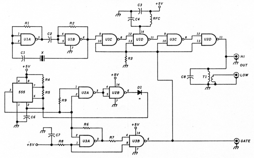
Figure 1 - 7.5-MHz pulse generator.
| C1 | 20-pF silver mica |
| C2 | 0.001 |
| C3,C4 | 0.01 |
| C6 | 0.47 µF |
| C7 | 0.1 |
| C8 | 33-pF silver mica |
| CR1 | 1N914 |
| R1, R2, R3, R4, R8 | 1 k |
| R5 | 1.5 MΩ |
| R6,R7,R9 | 470 |
| T1 | primary-30 turns no. 24 on 1/2", OD torold-Amidon T-50-2, secondary 2 turns no. 24 |
| U1,U2,U3 | 7400 |
| Xtal | 7.5-MHz crystal |
| RFC | 220µH |
The 7.5-MHz crystal came from my junkbox; the circuits are from QST(2) and The 555 Timer Applications Sourcebook with Experiments.(3) There's a broadly tuned circuit in the output which transforms the TTL voltage down to a usable value. I've provided outputs for the high and low level 7.5-MHz RF pulse and for the gate pulse. I built the generator on a Radio Shack perforated circuit board and mounted it in an aluminum box. I used a commercial 60-dB T pad attenuator with it to further reduce the generator low output.
The generator provided a calibrated "noise" pulse, similar to a static pulse in its effect on the receiver when connected to the antenna input. I observed considerable rounding off of the pulse envelope with the oscilloscope connected to the output of the 8.83-MHz, 455-kHz, and 100-kHz IF This is to be expected in any transceiver with a narrow bandwidth similar to the TS-940S.
After I made my preliminary observations, I decided to make some changes in the AGC circuit and get some onthe-air experience. Details of the TS-940S AGC circuitry (reprinted with permission from the Kenwood Service Manual) are shown in Figure 2. I've found it convenient to think of this part of the AGC system as being made up of four "sections" of related components. Table 1 lists the key components used in the various sections, along with their nominal functions.
An incoming IF signal provided at A of Figure 2 is rectified and doubled. A positive voltage is produced on the base of Q19. The voltage, which operates time constant sections 1, 2, and 3, comes from B and is established by setting the RF gain control. Current flows to 019 through R148 and R150. When the AGC is turned on, the drive to the AGC system at A sets the Q19 base voltage. This, in combination with the voltage from B and the drop through R148 and R150, establishes the collector current through 019. When 019 is driven harder by the IF signal (including noise pulses) Q19's collector goes down, dropping the voltage at the junction of R148 and R150. This causes the AGC circuits to react and lowers the AGC voltage at H to affect the transceiver's gain. The attack and decay of that voltage is determined by the components of the three sections.
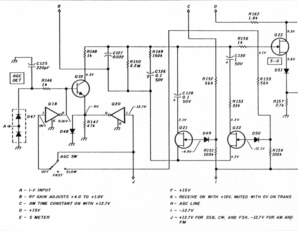
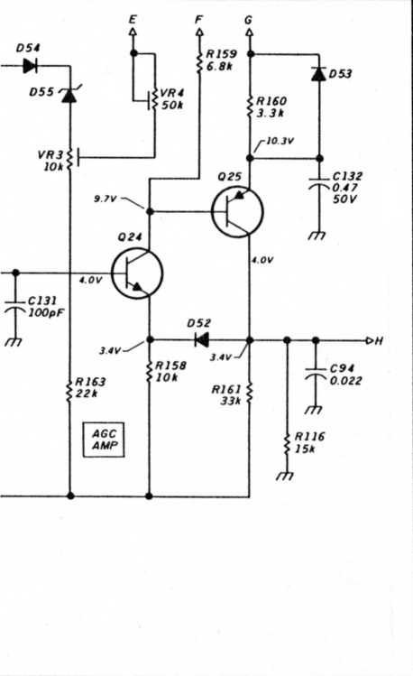
Figure 2 - TS 940S AGC system.
| Section | Components | Function |
|---|---|---|
| 1 | R148 (1.0 k) | attack and fast |
| C127 (0.22 µF) | AGC circuit | |
| R149 (68 k) | ||
| C126 (0.1 µF) | ||
| R150 (2.2 meg) | Q19 load resistor | |
| 2 | C128 (0.1 µF) | AM AGC time constant |
| 3 | C130 (1.0 µF) | slow AGC |
| R153 (33 k) | ||
| 4 | Q23 FET | AGC RC net isolation |
| Q24 | AGC amplifier/driver | |
| Q25 | AGC line driver, T/R |
In section 1, the attack and fast AGC components are fixed. They function in parallel with the slow components of section 3 when FET 022 is switched on in the slow AGC position by the application of +12.7 volts to R155. When the transceiver is switched to AM receive, +12.7 volts is applied to R152 at terminal C, toggling 021 on and connecting C128 in parallel with section 1. Kenwood recommends the slow AGC (sections 1 and 3) for most operating modes except AM.
This entire circuit has other functions beside supplying the AGC bus voltage at terminal H. For example, when you adjust the manual RF gain control, the voltage at terminal B varies from +4.0 to +1.0 volts and establishes an operating voltage to the RF and IF stages through the Figure 2 circuits. Also, when the transceiver is keyed to the transmit mode terminal G goes to 0 volts, reducing conduction through 025, causing H to be driven to -4.0 volts, and cutting off the receiving RF and IF stages.
Using these observations as a starting point, I considered how I might approach the task of improving the data communications performance of the transceiver without altering the equipment's general circuit performance and original design concepts.
I isolated the AGC system from the RF and IF stages of the receiver by applying the square wave gating pulse (no RF) directly to the AGC input at the Q19 base. I used a 10-meg scope probe to prevent circuit loading. Figure 3 shows how the original AGC system responds to the pulsed input as measured at terminal H. Under these test conditions (2.5 ms pulse at 2 Hz), the slow AGC position recovery time is less than that of the fast position. The longer the recovery time, the greater the probability that a bit of data will be lost.
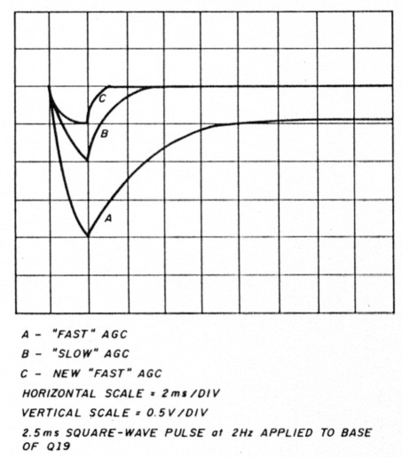
Figure 3 - Graphic display of oscillogram of AGC voltage developed with applied 2.5-ms pulse.
These measurements don't include the time required for the IF stages to respond to the AGC voltage, so I also made measurements with the 7.5-MHz pulse applied to the receiver antenna. They indicated that the RF output of the 100-kHz fourth IF followed the curves in Figure 3 closely. Test procedures maintained the signal below S9. Your operating procedures can also keep the input signal below S9 most of the time if you use the 30-dB input attenuator - an important part of the TS-940S.
In accordance with the design approach to reduce the AGC recovery time, I examined the RC time constants of section 1. Q19 load resistor R150 controls the recovery rate or discharge time for C127 and R149, the fast AGC circuit. Reducing the value of this resistor decreases the recovery time. I chose a value of 10 k. Figure 3 shows the recovery time when it's paralleled with R150. When the AGC RF-IF amplifier loop circuit is closed, the amplitude of the AGC voltage tends to be normalized due to the gain of the loop, and curves A, B, and C fall on top of one another - except for the recovery times.
Before I go on, I'd like to note that I found an error in my Kenwood Service Manual. The circuit diagram for the IF unit (X48-1430-00) doesn't agree with the pc board in my transceiver. The position of R150 was interchanged with R149 on the diagram in the manual. Figure 2 in this article shows them correctly. Some serial numbers of the 940 show R149 changed from 150 k to 68 k.
You could change R150 to 10 k permanently but this would also affect the slow AGC, and that circuit is satisfactory for all other modes of operation. I used an approach which didn't alter the original circuit or circuit board. There's an unused contact on the AGC switch in the fast position (see Figure 2). I used this to actuate the circuit shown in Figure 4. I've included a table of connections for application to the TS-940S that you can make without removing the IF circuit board.
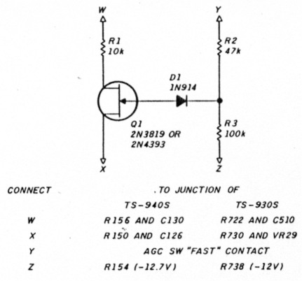
Figure 4 - New FAST AGC circuit for TS-940S and TS-930S.
When you move the AGC switch to the fast position, the gate of switching FET 01 is made positive and R1 is connected in parallel with R150. With the AGC switch in the slow position, the circuit is unaltered. Inserting a single pin connector in the Y lead lets you return the entire system to the original configuration by disconnecting that lead.
Construction and installation
The parts for the circuit in Figure 4 are mounted on a piece of Radio Shack circuit board slightly larger than a postage stamp. This is fastened to the IF unit with foam mounting tape.
Remove the bottom cover to access the IF unit, X48-1430-00. The location of every component is marked. You can make all connections to the IF unit on the exposed side of the board. Carefully clean the paint from the resistor leads and tack solder the wires of the new circuit to the exposed leads as indicated.
Remove the top and bottom covers to gain access to the contact on the AGC switch. Then remove two flat-head screws from each side of the front hinges so the front panel swings away from the chassis. Provide support for the front panel during this step to prevent damage to the panel or controls. Solder the wire lead Y shown in Figure 4 to the spare contact using a small iron and low heat. Use the TS-940S service manual to locate the IF unit and the component parts.
Recommendations for modifying the TS-930S
I did much of my initial work and record keeping with the TS-930S, before the TS-940S became available. As far as recovery time is concerned, I found the performances of the AGC systems much the same. The TS-930S AGC systern may be modified using the same principles I used for the TS-940S. Figure 5 is the TS-930S AGC system shown in the service manual. This system is very similar to the TS-940S. Operation is the same as that of the TS-940S and doesn't warrant additional explanation. The AGC switch is the same in the two models, so there is a spare blank contact available to operate the new fast AGC circuit. The table in Figure 4 shows the connections to the TS-930S for the new circuit.
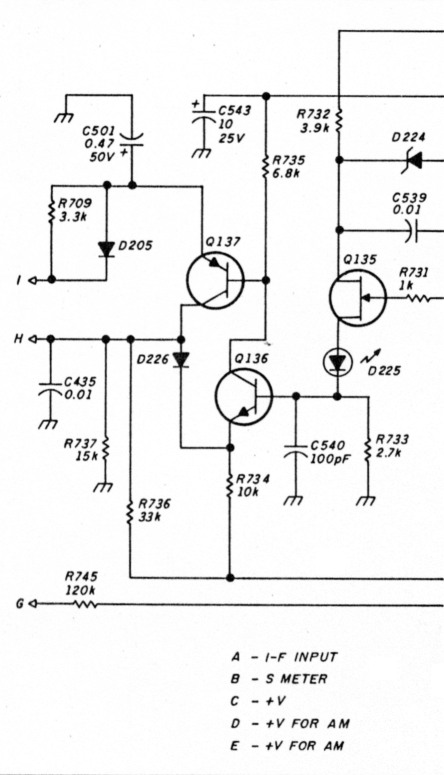
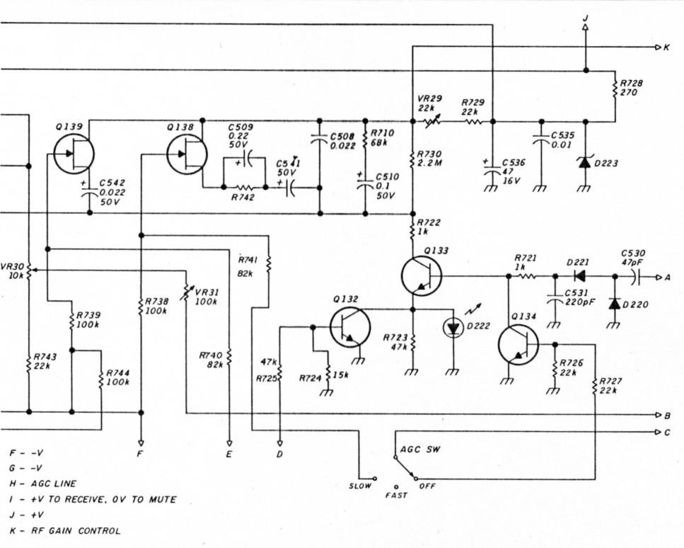
Figure 5 - TS-930S AGC system.
On-the-air testing
Preliminary tests showed that the 8.83-MHz filter is "shock" excited to oscillation at its resonant frequency by the 7.5-MHz pulse applied to the receiver antenna. This lengthened the pulse and countered the short recovery time by increasing it. Oscillation occurs whether the slow AGC is on or the AGC is off; it just becomes more obvious with the new fast AGC. Static pulses act in the same manner to cause oscillation.
I then investigated the noise blanker to determine if it would act to blank such pulses and prevent the oscillation from degrading the recovery time. (Noise blanking occurs before the 8.83-MHz filter.) NB2 was very effective in blanking the repetitive 7.5 MHz-pulse and in blanking similar single static pulses. Not all static was blanked, but not all static causes ringing. The noise blanker does act to prevent oscillation; set the level control between 0 and 2 for best results.
The slow AGC figure of merit, the change in audio output with increased signal strength,(4) is 0 dB for signal levels from 1.55 µV to 1.55 AV + 110 dB. The new fast AGC causes an increase of 3 dB for the same signal range. This isn't significant.
My RTTY reception improves dramatically when I use the now fast circuit during the noisy summer months. Fast fading effects are reduced - the circuit recovers fast enough to compensate. I do notice a raspy quality on voice communications. This isn't a problem on RTTY because the signal is like a continuous carrier. When an adjacent SSB signal tends to control the AGC and prevent reception of the wanted on-channel signal, I can switch on the new fast AGC. This allows copy between voice peaks of the other signal, and generally works unless the other station turns on its voice processor. If conditions are good, I switch on the slow AGC for the best voice quality. However, the new fast AGC outperforms the slow one for DATA/RTTY reception.
Acknowledgments
I'd like to thank Allen P. Haase, W2ECA, and John A. Kienor, W8AVH, for their expert assistance in the preparation of this article.
References
- Ulrich Rohde, "Understanding and Handling Nose;" HAM RADIO. November 1986. page 10.
- Ken Powell. "The Weekerder-A Simple Crystal Calibrator;" QST. July 1979. page 38.
- Howard M. Berlin, The 555 Timer Applications Sourcebook with Experiments, Sams. page 107.
- Wes Hayward and Doug DeMaw. Solid-State Design lot the Radio Amateur, ARRL, page 94
W8WFH, W. C. Louden.