Atmospheric optical propagation
In this, the final part of a series of columns on laser communication, I'll take a look at the atmospheric propagation of light. While there are many propagation modes for RF energy - like E skip, meteor scatter, line of sight, troposcatter, and ducting - there's only one mode of propagation for light that's of practical importance in optical communication. This mode is line of sight. While propagation via tropospheric scattering is possible, the equipment needed (several watts of laser power and lenses or mirrors many feet in diameter) is beyond the reach of Amateurs. The only non lineof-sight mode of optical propagation which could be within the reach of Amateurs is a form of ducting known as a mirage. It occurs when layers of air of very different refractive indexes cause light to bend around the curvature of the earth. If you can recall the number of mirages you have seen, you'll get some idea of the low probability of using this propagation mode for laser communication!
Restricting the discussion to line-ofsight propagation, you must first ask what effects the atmosphere has on a laser beam. For example, does the atmosphere absorb light? At visible wavelengths, there's no significant absorption of light. This isn't true in the ultraviolet and infrared regions, but we're only concerned here with visible light. Another effect of the atmosphere on light propagation is due to turbulence. Stars "twinkle" not because they vary intrinsically in brightness, but because their light undergoes rapid intensity and positional changes as it passes through the unhomogeneous atmosphere. Similar effects may be observed on a laser beam passing through the atmosphere. However, for the simple . communications system described here, they will not affect the received signal as long as they aren't so severe as to result in a laser beam deflection great enough to cause it to miss the receiver for a significant fraction of time. This is very unlikely to occur and can be disregarded for all practical purposes.
Scattering is the only atmospheric effect on light propagation of significant importance to a simple optical communications system. Light which is scattered by the atmosphere is prevented from reaching the receiver and results in received signal attenuation. There are two causes of atmospheric scattering. First, there's scattering by the molecules of the air itself. This is fairly constant and can be described by the process of Rayleigh scattering (scattering by elements much smalls* than the wavelength of tote tedietiOn being scattered). Second,there's scattering by particulates in the atmosphere - water droplets and dust particles, for example. This type of scattering is highly variable and is the cause of smog and haze, with which we are all familiar. It can be described by the process of Mie scattering (scattering by elements similar in size to the wavelength of the radiation being scattered). Both types of scattering result in higher losses for shorter wavelengths; that is, blue light is scattered more than red light. This is why the sun (and often the moon) appears very red when rising or setting. The red light penetrates the atmosphere with less scattering losses than the blue light. Similarly, the sky is blue because we are seeing the preferential scattering by the atmosphere of blue light.
In addition to scattering, the other significant process which gives rise to signal loss on a line-of-sight path is due to the geometric spreading of the laser beam. If you know the path length, the divergence of the beam, and the size of the receiving optics, you can calculate how much of the original laser power will be collected by the receiver using simple geometry that Ill describe later. If a beam expander is used, then the transmissivity of the optics involved must be taken into account, but this is usually just a small correction.
If you're interested in the details of the calculations involved, read the appendix to this month's column. The math is simple geometry and algebra, but I won't inflict it on those it might scare away!
The most important variable in transmission is the clarity of the atmosphere. In my area, New Jersey, visibility of 20 miles (as noted in local weather reports) is not uncommon. I have heard reports of 50+ mile visibility while in Maine, and on a recent trip to California I heard a weather report claiming 100-mile visibility in the Sacramento Valley.
Using the formulas given in the appendix or the graphs derived from them to calculate the range of a typical system, you should come up with the following:
- Laser power = 1 mW
- Laser beam divergence = 1 mR Laser wavelength = 632.8 nm (He-Ne)
- Diameter of receiving optics = 8 inches
- Transmissivity of receiving optics = 0.9
- Detector sensitivity = 1 x 10⁻¹⁰ watts
- Visual range = 32 km (20 miles)
The DX range at a 0-dB signal to noise ratio is 49 km. This reduces to 45 km for a 3-dB ratio and to 40 km for a 6-dB ratio. Doubling either the laser power, receiving optics area, or detector sensitivity will only increase the 0-dB S/N range to about 54 km. Multiplying any one of these same factors by 5 yields an increase in range to 61 km. However, an improvement of only 25 percent in visual range (to 40 km) yields a DX range of 58 km with the original equipment parameters. Waiting for a slightly clearer day can result in the same difference in potential range as will a large change in equipment, and small increases in distance can make a big change in signal strength. Note that using blue light (440 nm) in place of red indicates a reduction in range of around 40 percent under these conditions.
I hope that this analysis gives you some idea of the capabilities of modest laser communications systems and the factors important to performance. The numbers calculated should be used only as a guide, because the calculation of scattering losses on the basis of "visual range" is only an approximation.
Appendix
To calculate the strength of a laser signal over a given path, you need to know the following:
- The laser power
- The beam divergence
- The transmissivity of any beam expander
- The path length
- The transmissivity of the atmosphere
- The area of the receiving optics
- The transmissivity of the receiving optics
All of these factors are known (or can be reasonably estimated) with the exception of the atmospheric transmissivity loss factor. This factor can be calculated using the formula:

where M is the Mie scattering coefficient (km-1),
R is the Rayleigh scattering coefficient (km-1),
D is the path length (km), and (M+R) is the atmospheric attenuation coefficient.
You can estimate the scattering coefficients using empirically derived relationships. The Rayleigh scattering coefficient is given by the expression:
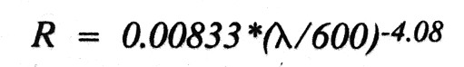
where X is the wavelength of the laser light (nm).
The Mie scattering coefficient is given by the expression:
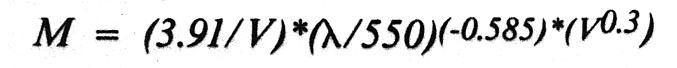
where V = the visual range (km).
Visual range is a measure of how far you can see, based on the apparent contrast observed in a standard target at a given distance. It's often given in weather ,reports and aviation weather forecasts. It may be estimated on the basis of the following qualitative descriptions.
| Conditions | Visual range (km) | Atmospheric attenuation coefficient (km-1 at 632 nm) |
|---|---|---|
| Extremely clear | 100 | 0.03 |
| Very clear | 40 | 0.08 |
| Clear | 20 | 0.16 |
| Light haze | 7 | 0.49 |
| Haze | 2.5 | 1.40 |
This information is also depicted graphically in Figure 1.
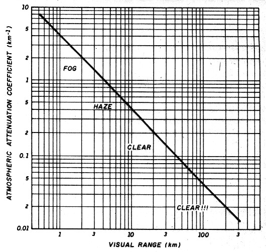
Fig 1: Relationship between visual range and atmospheric attenuation coefficient. Values ww approximate. They will be about 10 percent lower at the red end of the spectrum and about 20 percent higher at the blue end.
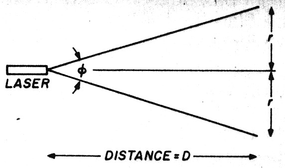
Fig 2: A graphic depiction of the laser beam dhow gence illuminating an area.
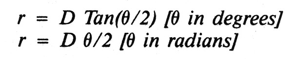
Referring to Figure 2, you have a laser of power P watts and beam divergence O radians illuminating an area of radius r km at a distance of D km.
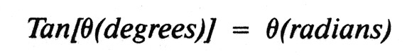
For small angles,
The radius, r, of the illuminated circle at a distance, ID, is given by the relationships:
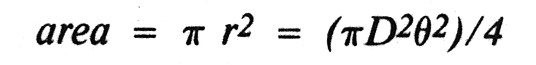
The area illuminated will therefore be given by the relationship:
The power density at the target is given by power/area and is therefore (assuming uniform illumination):
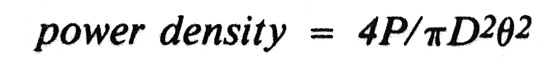
(In fact the power density will be somewhat higher if the laser is aimed accurately, because the illumination isn't uniform across the beam but peaks in the center. Thus, this is a conservative estimate.)
For a detector capturing light from A (area of lens or mirror), the power received will be given by:

And, if To is the transmissivity of the optics and Ta is the transmissivity of the atmosphere, then the power incident on the detector will be given by:

If the detector can detect a minimum signal power Dp, then at the maximum communication distance D:
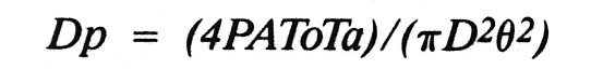
Rearranging this, you have:
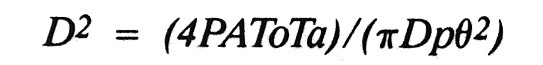
The only unknowns in this equation are D, the maximum communications distance, and Ta, the transmissivity of the atmosphere. Ta can be determined as described above, and so D can be calculated.
Ta is given by the expression:
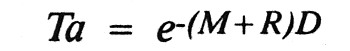
where e = 2.71828, M is the Mie coefficient, R is the Rayleigh coefficient, and (M+R) is the combined atmospheric attenuation coefficient.
Thus, the final expression for calculating maximum distance is:
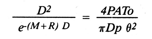
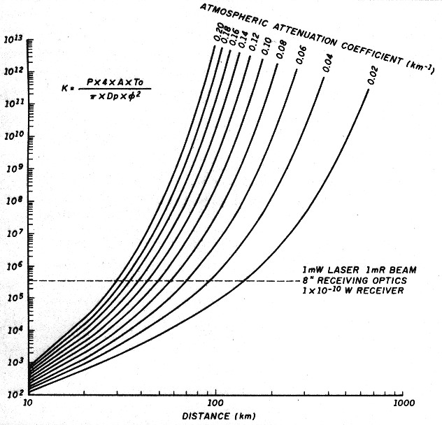
This isn't a trivial equation to solve. It can be solved graphically using Figure 3, where the right-hand side of the equation is plotted against DX potential for a number of different scattering conditions. Note that units must be consistent. Here's an example: for distance in km, the area of the receiving optics (A) must be expressed in square km, the atmospheric attenuation factor (M+R) must be in units of km-1, and all power and sensitivity factors must be expressed in the same units (watts). Perhaps the easiest solution for those with access to a computer is to use a trial and error method. Because all quantities except D are known, substitute increasing values of D into the equation until both sides are equal. A TURBO BASIC listing* is available which uses this formula to calculate DX range (at 0-dB signal to noise ratio) for a given atmospheric communication system. The program should also run under QuickBASIC, but to run under more traditional versions of BASIC (like GW-BASIC) some modifications, like the addition of line numbers, the replacement of labels with line numbers in the GOTO statements, and the REM keyword before the remarks, will be required. A compiled version of this program which will run on any IBM PC compatible machine is available from the author for $5 to cover materials and shipping.