Slim Jim 2 metre aerial
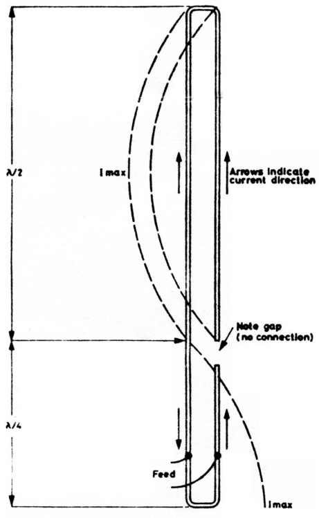
Fig. 1: The basic aerial, showing direction of current lbw and phase reversal in matching stub.
This is a vertically polarised omnidirectional free space aerial for two metres but which will operate in the same way for higher or lower frequency bands by scaling the dimensions accordingly. It has a radiation etlIciency 50% better than a conventional ground plane due to its low angle radiation, is unobtrusive, has no ground plane radials, and therefore has low wind resistance. The name "Slim Jim" stems from its slender construction (it is only 60 inches long for 2 metre operation) and the use of a J type Integrated Matching stub (JIM) that facilitates feeding the aerial at the base, thus overcoming any problem of interaction between feeder and aerial. The feed impedance is 50 ohms.
How the 2BCX "Slim Jim" operates
Basically it is an end-fed, vertically operated, bolded dipole (Fig. 1). As with all folded dipoles, the currents in each leg are in phase whereas in the matching section they are in phase opposition, so little or no radiation occurs from the matching stubs. Correctly matched the VSWR will be less than 1.5 to 1 and will remain so across the band. It can be constructed for use as a fixed home station "omni" or for portable operation. and the aerial has been used for mobile operation mounted on a short stub mast attached to a rear bumper; at sea a special version is used, completely enclosed in a plastic tube for protection against salt water.
Construction
The "Slim Jim" may be constructed from 1/4 or 3/8 inch diameter aluminium tube, stiff coathanger (galvanised iron) wire or 300 ohm ribbon feed. The spacing between the parallel elements is not critical and neither is the overall length, providing this is within 1/4 inch.
Details for a strongly made version for fixed station use outdoors are given in Fig. 2, in which the diagrams are self-explanatory and dimensions are included. The only comment called for is on the insulation between the return half of the folded radiator and the top of one side of the matching stub. This may bit a piece of thick perspex, tufnol or p.t.f.e. drilled to take the rods (they must not touch), which can be set in with Araldite.
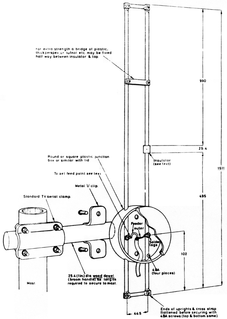
Fig 2. Main constructional details
Response
The polar diagrams shown in Figs. 3 and 4 explain the "Slim Jim's" improved efficiency over the 5/8 wavelength ground plane, in spite of its claimed 3dB gain over a dipole or similar ground plane. Fig. 3 shows that the "Slim Jim" vertical angle of radiation is almost parallel to ground, so maximum radiation is therefore straight out (and all round) which is what we want. With all ground plane aerials, including those with radials of more than ½ inch length, radiation is tilted to an average angle of 30° or more. The dotted line in Fig. 3 is that from a 5/8 wavelength Gr.P aerial with 6 quarter-wave radials.
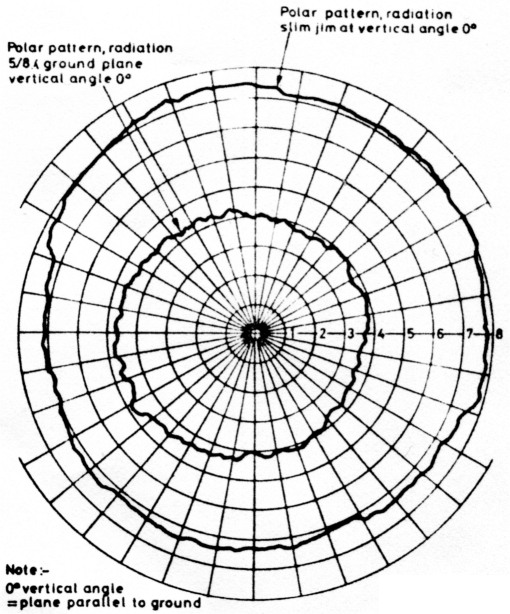
Fig. 4: Providing omnidirectional patterns of a 5/8 gr.p. at 0° vertical angle. Both patterns from models at 650MHz.
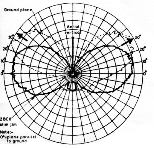
Fig. 3: Where the 5/8 wavelength ground plane radiation angle is 30° or more (dotted line), and the "Slim Jim's" at vbtually 0°.
Now examine Fig. 4. The outer line is the (omnidirectional) radiation from the "Slim Jim" at a vertical angle of 0° e.g., on a plane parallel to ground. The inner line shows the loss of radiation, by comparison, from a 5/8 wavelength ground plane at the same angle and that loss can be around 6dB! This has been verified with full size 2 metre aerials as well as with UHF scale models on the writer's aerial test range. Many 2 metre operators already using the "Slim Jim" in place of a ground plane will confirm its efficiency.
Setting up
The feed point may be protected from rain as shown in Fig. 2, by a circular plastic junction box, with a screw-on lid, but the correct feed point must be found first. The best way of doing this is to complete the construction of the aerial and stand it upright in the room near the transmitter but clear of other conductors. Use the full length of feeder required to reach the aerial when finally in situ. Clip on at about 4 inches up from the bottom as in Fig. 2. Adjust slightly up or down for minimum S.W.R. and maximum power into the aerial. Note points of contact and then fit solder tags as shown ready for the feeder soldered connections. The plastic box may now be fitted and the completed aerial and feed protector box can be given a coat or two of polyurethane varnish before final installation. Fig. 2 shows methods of mounting on a mast with a TV aerial claw clamp such as those made by Antiference.
Positioning of the "Slim Jim"
Ideally the aerial should be as high as possible and clear of other aerials or conductors. It will. however, operate quite well indoors in the loft, or even in a living room, but obviously with a lower range.
If the "Slim Jim" is constructed from coathanger wire, galvanised iron wire or 300 ohm ribbon feeder, while other considerations remain the same, the space between the elements may be reduced to about 1 inch. The whole of the aerial, made like this, could be housed in plastic water pipe. Being compact, the "Slim Jim" can be carried around quite easily for portable operation on holidays, etc. Please note the name "2BCX Slim Jim" is copyright and the design is exclusively that of the writer.
G2BCX, F. C.Judd.