Restoration of old valve receivers
Whilst not pretending that valve sets are superior Robert A. Wilson recalls the fun in valve receivers.
With the great advances in technology over the last few years, the use of the valve in radio receivers has been dropped in favour of the transistor.
For a lot of people, including myself, these advances have unfortunately taken away a lot of the pleasure of former times when dealing with radio sets.
Recently I have obtained and resurrected two ancient sets. The fault diagnosis and repair did not take a great deal of time or money, but it gave me a lot of pleasure in recalling my earlier delvings in radio.
The purpose of this article is not to pretend valves are superior to more modern sets, but to re-kindle old memories amongst senior readers and maybe give some of the younger readers a practical insight into the radio of days gone by.
The sets themselves are neither expensive, or difficult to obtain. Markets, car boot sales and jumble sales usually provide a selection of sets to choose from.
I would say that a reasonable price range would be between five and ten pounds. When looking for a suitable set a few points should be kept in mind. Valves are often difficult to obtain and quite expensive these days. Make sure that the set you choose is complete, unless you know that you can obtain any missing valve or item.
I prefer to work on the old mains sets as with battery sets the batteries would be very expensive, if indeed high voltage batteries are still produced anyway. Also the battery valve was much more delicate and susceptible to filament failure through either misuse or physical knocks.
Quite often the type of valve used in the set was printed on the back panel. This is very useful when deciding what to buy as you can always take a copy of PU/along with you for a quick check in the valve adverts as to whether they are still available should any be gone.
Having obtained a set, a few preliminary checks should be made before plugging in. Have a good look for any obvious burn marks above or below the chassis. The inside of all the valves should have a mirror-like mark somewhere inside the glass envelope. This is normal and not an indication of a "burn out". If the inner coating of the valve is milky white, this indicates that the glass envelope has leaked air and the valve therefore rendered useless.
Check the resistance across the mains cable. If there is a dead short, there is no point in plugging in until it has been cleared. If the set is one using a mains transformer the resistance could be as low as 40 or 50Ω. Any a.c./d.c. sets use a dropping resistor which is usually quite large (several inches long) and green in colour. The mains cable resistance of an a.c./d.c. set should be considerably higher, more like 2.5kΩ. The reason for this is that all the valve heaters (filaments) are connected in series with the dropper resistor. So that if the valves took 0.1A for their heaters from a 250V supply the total resistance would be 2.5kΩ.
Next Steps
If you do not obtain the expected reading you should look for the simple things first, such as burned out fuses, faulty on/off switches. The older type of mains transformer seldom gave trouble, but fortunately replacements are still available at reasonable cost. On the a.c./d.c. sets, however, the mains dropping resistor could well be the reason for an open circuit. If it is not the resistor then it must be either fuses, switch or one of the valve heaters open circuit.
Once these preliminary checks are complete, the set may be plugged in and switched on. Be careful of course not to touch the chassis, or any other metal part of the set when plugged in to the mains.
The first thing to look for in a valve set is whether the valves are lighting up or not. If any of the valves fails to light, the set will not work.
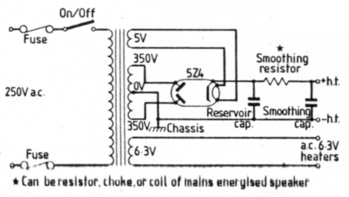
Fig. 1: A typical power supply for a set using a mains transformer
A typical power supply unit for a set using a mains transformer is shown in Fig. 1. If you have a data sheet for your set all the better, but they are mostly very similar and it is quite possible to get by with common sense. If none of the valves light, you should first check that the mains voltage is reaching the transformer. If it is, the heater volts should then be checked on the secondary. Heater voltages vary, but are generally quite low, usually 6.3V in a set using a transformer. The heater volts can be obtained from a valve data book. Check the heater connections on the valve base. If only one valve fails to light, this would suggest heater failure, but do not jump to conclusions. It could be a broken wire, dry joint or dirty base pins. All glass valves should be removed by gently pulling them out with a slight rocking movement. Older valves with a plastics base should be removed in the same manner, but making sure that you have hold of the base and not the glass. If you try pulling them out by the glass you could well end up pulling the glass from the valve base, thus ruining the valve.
A typical power unit of an a.c./d.c. set is shown in Fig. 2. In this system, it is obvious that failure of fuse, switch, dropping resistor, any dial lamp or any valve will result in nothing lighting up.
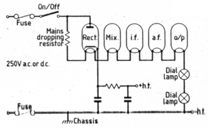
Fig. 2: Typical power supply of an a.c./d.c. set
Both types of valve heating circuits are so simple as to be self explanatory.
High tension (h.t.) faults, however, are quite common in these old sets and so I will describe the problems I had recently with the set shown in Fig. 3. When I first purchased it 1 knew there would be power problems as the socket for the reservoir/smoothing capacitor was empty. These capacitors are usually quite large, often standing as tall as the valves and i.f. cans. Also the rectifier valve, a 5Z4, was missing. When the set was first switched on the four remaining valves lit up as expected (heater failures are rare). On removing the set from the case I discovered that at some time the reservoir/ smoothing capacitors, once contained in the single can, had been replaced by two smaller ones now housed beneath the chassis. Not wanting to go to the expense of another rectifier valve I replaced the missing valve with a pair of 400V 1 A silicon diodes. On plugging in and switching on the set worked after a fashion. But after a few minutes a bubbling sound was heard from the mains transformer, accompanied by a burning smell. Even with the h.t. lead disconnected from the radio it still overheated after a few minutes. Closer inspection of the bottom of the transformer showed signs of previous burning and I had to accept the fact that the transformer was faulty.
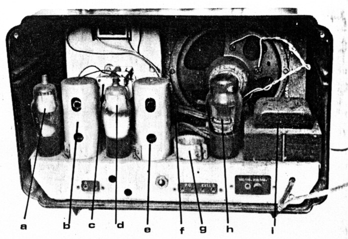
Fig. 3: A typical commercial receiver of 30 years ago. (a) Frequency changer (mixer) 6K8. (b) Intermediate frequency transformer (i.f. can). (c) Tuning capacitor. (d) Intermediate frequency (i.f.) amplifier 6K7. (e) Tuning slug of i.f. transformer. (f) Detector, a.g.c., a.f. amplifier valve 6Q7. (g) Empty socket once containing reservoir/smoothing capacitors. (h) Output valve 6V6. (i) Mains transformer, 250V primary, 350-0-350, 6.3, and 5V secondaries.
Fortunately I had a similar transformer previously salvaged from a junk set. When this was fitted the set worked at a more acceptable level of volume and more important without overheating. The new power unit circuit is shown in Fig. 4.
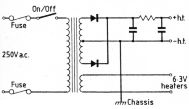
Fig. 4: The new power unit for my receiver
Had the set been of the a.c./d.c. variety and had a burned out mains dropper for which a substitute could not be found, a new power unit could have been built on these lines. The biggest problem in doing this would be to find correct heater voltages. For instance a set recently worked on had five valves with heater voltages of 14V, 12.6V, 14V, 45V and 31V. The 31 V valve was the rectifier which could be easily disposed of by replacing with a silicon diode. A transformer with an output of 40V could then be used to take care of the other four valves. The 45V output valve would have to manage with just 40V. The other three would be connected in series with each other, the three requiring a total of 40.6V.
Knowhow & Sense
So it can be seen that with some common sense, plus a knowledge of power supplies in general, the problems of power requirements can be overcome without too much trouble.
The remainder of the citcuitry will be very similar for either transformer sets or a.c./d.c. ones.
A typical valve-line up for a domestic receiver is: frequency changer (mixer), i.f. amplifier, detector/ a.g.c./a.f. amplifier and output stage. The mixer is usally a triode-hexode, the i.f. a variable mu pentode, whilst the detector/a.g.c./a.f. are combined in one valve, a double diode triode. The output stage will be either a pentode or a beam tetrode.
High Quality Sets
Occasionally in high quality sets there would be an r.f. amplifier before the mixer and an additional i.f. stage.
Identification of the valves is obtained from a radio valve data book which usually lists all the various types together. The set shown in Fig. 3 has a class of valve once in very common use and they identify as follows:
- 6K8 triode hexode mixer
- 6K7 variable mu pentode
- 6Q7 double diode triode
- 6V6 beam tetrode
These are good valves to work with as they are still available and all have 6.3V heaters.
Another common set of valves usually to be found in a.c./d.c. sets are:
- UCH42 triode hexode mixer 14V heater
- UF41 variable mu pentode 12.6V heater
- UBC41 double diode 14V heater triode
- UL41 pentode 45V heater
- UY41 rectifier 31V heater
For safety reasons, and also valve/ component availability, the a.c. only sets are the best to work with. They usually have an earthed chassis and are isolated from direct connection from the mains by the transformer (although dangerous voltages are still present within the set).
The a.c./d.c. types have a "live" chassis, connected direct to the mains.
Once power has been confirmed/ restored, if the set still does not work we must go further.
It goes without saying that all the dust has been removed. These old sets are usually thick with it and although it doesn't often prevent them from working it can lower their general performance and also become a fire hazard. Certain components will only very rarely give trouble, provide they are not tampered with-the tuning coils, mixer coils and i.f. transformers. The tuning and mixer coils are usually situated below the chassis in the vicinity of the tuning capacitor. The i.f. transformers are in large cans usually between the valves. In Fig. 3 the holes in the i.f. cans give access to the dust iron tuning cores. It is usually obvious if they have been tampered with, as after the initial setting up they are sealed with either wax or paint. Once set up in the factory they remain correct, so never attempt to alter them unless you have reason to believe that they have been tampered with. The same goes for the other coils-leave them alone!
Still Not Working?
The tuning capacitors in these old sets are air-spaced and as long as their vanes are not touching the only thing they are likely to suffer from is dust. If present if should be removed by gently brushing with a fine brush.
If the set is still not working, or working at reduced performance, the individual valve power supplies should be checked. The mixer should have a fairly large anode voltage on both the triode and hexode sections and on the common 2nd and 4th grids of the hexode section there should also be a good voltage, although slightly less than the anode volts.
The i.f. amplifier should also have a high anode voltage and a fairly high 2nd (or screen grid) voltage. The 3rd grid should have no voltage or very little. The double diode triode should only have a high voltage on the anode of the triode section. The output valve if it is a pentode may have the anode and screen grid strapped together, in which case a high voltage should appear on both. The 3rd grid (suppressor) should again have little or no voltage. A beam tetrode (no suppressor grid) should be similar.
Screen grid circuits can often give trouble. They are connected to the h.t. line by a resistor and also decoupled to earth by a capacitor. Should the capacitor break down and short the screen grid to earth, the resistor will overheat and burn out. Should this happen, the valve usually survives, but will not function at optimum performance until the screen grid voltage has been restored.
Should any of these voltages not be present it is a matter of common sense to find out why. The anodes are all connected to the h.t. line by either a transformer primary or a resistor, and the cathode to earth either direct or via a resistor or coil. If all the voltages are present at the anodes and screen grids, the cathode circuits should be looked at. If the cathode is joined directly to earth there is no problem. If it goes via a small resistor or choke, check them on the ohmmeter. Cathode resistors often have a small capacitor across them for decoupling. If this capacitor develops a short the set will continue to work, but not at optimum as the bias arrangements are upset.
A check can be made on the a.f. stages by injecting an audio signal to the grid of the output valve. If the amplified signal comes out of the speaker, try putting it into the grid of the triode. These two grids are the signal grids, in the case of the triode the only one, in the case of the output valve G1.
Coupling Components
Coupling components can also give trouble and prevent a set from working even when all voltages seem OK. They usually take the form of small wax covered capacitors in the region of lOnF. These waxy types often develop leaks after a number of years and can be checked on the ohmmeter in the usual manner.
Wirewound resistors should always be suspected as they often give trouble. They are usually quite heavy looking things, painted green or buff colour with the value and wattage printed on them rather than in colour code.
Older valves as shown in Fig. 3 often have a connection made to the top via a small clip. These caps are usually grid connections, one of which goes into an i.f. transformer. In this instance the connection is made by a single wire, but in some sets it is coaxial cable. Very old coaxial cable can develop short circuits and prevent the set from functioning, also with the grid caps being taken off and on sometimes the wire breaks inside the can. The cans may be opened fairly easily. Sometimes there are two nuts below chassis, or in this case two spring clips. Always built well in those days were i.f. transformers, and the windings terminated in a solder tag before changing to either coaxial cable or normal wire to the valve. As a result, repair is quite easy. But apart from connection repair, an i.f. can should be left alone. If necessary the primary and secondary and insulation may be checked from the external connections.
With the larger type of valve, the pins usually remain quite clean and poor contacts are rare. With the smaller all glass ones, however, the pins tend to get quite black and poor connections can result. These should be scraped gently with a sharp knife.
If you do not have a circuit of the set it is a good idea to write the number of each valve on the chassis next to its socket. Also when cleaning valves take care to note the number beforehand, then in the event of rubbing it off it can be put back on again with a sticky label.
Last Point
One last point. In very old sets the speaker may be mains energised, rather than having a permanent magnet. In a mains energised speaker the magnet winding is also the smoothing choke from the power unit. This can be confusing if you have not come across it before as the speaker has four wires coming out of it, two going direct to the smoothing capacitors.
Once these ancient sets are restored to the full working order most people are surprised at their excellence of tone and general performance. They are well worth the effort of repair, as they say-a change is as good as a rest!
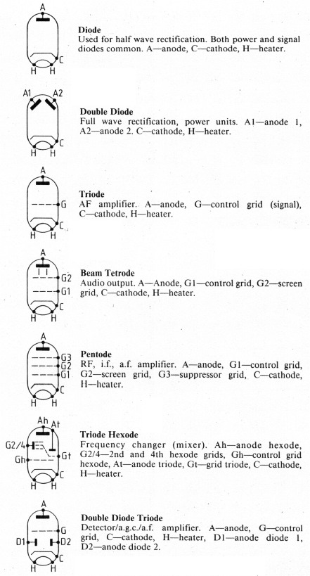
Fig. 5: Types of valve once in common use
Typical Voltages (Valves Bases)
The following voltages were taken from the Philco set shown in Fig. 3, using a digital meter (chassis negative);
| h.t. supply 335V | |
|---|---|
| 6K8 frequency changer (mixer) | |
| Cathode | 3V |
| Screen grid | 85V |
| Anode hexode | 332V |
| Anode triode | 135V |
| 6K7 i.f. amplifier | |
| Cathode | 2V |
| Screen grid | 85V |
| Anode | 326V |
| 6Q7 detector/a.g.c./a.f. amplifier | |
| Cathode | 3V |
| Anode | 185V |
| Anode diode | 2V |
| Anode diode | 1 V |
| 6V6 output | |
| Cathode | 8V |
| Screen grid | 335V* |
| Anode | 325V |
* The screen grid of the output valve in this set is taken to the h.t. line, hence the higher voltage on the screen than the anode.
All of these voltages will vary from set to set, but do give a good idea of what to expect.
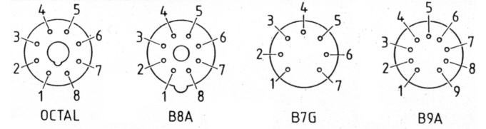
Fig. 6: General information. The four bases show the most common types of valves. The tables shows a selection of typical valves. For more information a valve data book should be consulted
| Triode Hexodes | ||||||||||||
|---|---|---|---|---|---|---|---|---|---|---|---|---|
| Pins | ||||||||||||
| Number | Base | 1 | 2 | 3 | 4 | 5 | 6 | 7 | 8 | 9 | Top | Heater V |
| UCH42 | B8A | H | Ah | At | Gt | G2 | G1 | C | H | 14 | ||
| 6K8 | Octal | - | H | Ah | G2 | Gt | At | H | C | 6.3 | ||
| X79 | B9A | G2 | G1 | C | H | H | Ah | Gt | At | - | 6.3 | |
| ECH81 | B9A | G2 | G1 | C | H | H | Ah | G3 | At | Gt | 6.3 | |
| ECH35 | Octal | - | H | A | G2 | Gt | At | H | C | G1 | 6.3 | |
| Pentodes | ||||||||||||
| 6K7 | Octal | - | H | A | G2 | G3 | - | H | C | G1 | 6.3 | |
| UF41 | B8A | H | A | - | - | G2 | G1 | C | H | 12.6 | ||
| EF80 | B9A | C | G1 | C | H | H | - | A | G2 | G3 | 6.3 | |
| EF39 | Octal | - | H | A | G2 | G3 | - | H | C | G1 | 6.3 | |
| W77/EF92 | B7G | G1 | C | H | H | A | G3 | G2 | 6.3 | |||
| Double Diode Triodes | ||||||||||||
| 6Q7 | Octal | - | H | A | Ad | Ad | - | H | C | G1 | 6.3 | |
| EBC33 | Octal | - | H | A | Ad | Ad | - | H | C | G1 | 6.3 | |
| UBC41 | B8A | H | A | G1 | - | Ad | Ad | C | H | 14 | ||
| DH77/6AT6 | B7G | G1 | C | H | H | Ad | Ad | A | 6.3 | |||
| Output Tetrodes and Pentodes | ||||||||||||
| 6V6 | Octal | - | H | A | G2 | G1 | - | H | C | 6.3 | ||
| N78 | B7G | G1 | C | H | H | A | - | G2 | 6.3 | |||
| UL41 | B8A | H | A | - | - | G2 | G1 | C | H | 45 | ||
| Power Rectifiers | ||||||||||||
| 5Z4 | Octal | - | H | - | A | - | A | - | H/C | 5 | ||
| UY41 | B8A | H | A | - | - | - | - | C | H | 31 | ||
| U78/6X4/EZ90 | B7G | A | - | H | H | - | A | C | 6.3 | |||
| Ah | Anode hexode |
| A | Anode |
| G1 | Control grid |
| G2 | Screen grid |
| G3 | Suppressor grid |
| At | Anode triode |
| Gt | Grid triode |
| Ad | Anode diode |
| C | Cathode |
| H | Heater |
| - | Not connected |
Note: sometimes in pentodes the suppressor grid (G3) is connected to the cathode within the valve, hence no external connection.