Practical antenna electrometer
Most people regard atmospheric static as an unavoidable nuisance, few have ever thought of this effect as a useful weather forecasting aid or even a means of monitoring ionospheric conditions. Tony Hopwood is one of these few enlightened people, and in order to monitor this natural phenomenon he has produced the instrument described here.
Static is a fact of life for radio enthusiasts. Not only does the background fizz and crackle of a storm blanket DX reception. but it can become a real hazard when an antenna takes a kilovolt charge from a passing thunderstorm, or unusual atmospheric conditions.
A well-insulated wire antenna is an efficient collector of the atmospheric electric charge, and monitoring that charge gives a fascinating and accurate insight into present and future local weather conditions.
Because the atmospheric electrical field has a fair-weather source impedance of over 10TΩ (a Teraohm is 1012 ohms) it can only be monitored by a high input impedance device. It is easy to build a portable and sensitive low voltage electrometer using m.o.s.f.e.t.s. but unless a stable gigohm input bias resistor is used, the instrument will only show relative field measurements. and may overload when the antenna takes a charge of more than a few volts.
Practical design
A practical antenna electrometer must have a high input impedance and be able to follow an input that can swing hundreds of volts positive or negative with respect to earth. It must also read accurately and be immune to damaging transients from nearby lightning strikes.
A single triode valve operated in cathode-follower mode, hung between stabilised positive and negative h.t. (high tension) rails will do all this. as well as providing a self-calibrating readout of most atmospheric conditions.
The circuit as shown Fig. 1 is very simple and uses three valves. one triode and two stabiliser tubes. The author's choice of valve was a 6Q7GT type. mainly because it is still available new, plus it has a top cap grid connection making it easy to maintain a high input impedance. However. any indirectly heated. top cap grid triode or triode strapped pentode would serve.
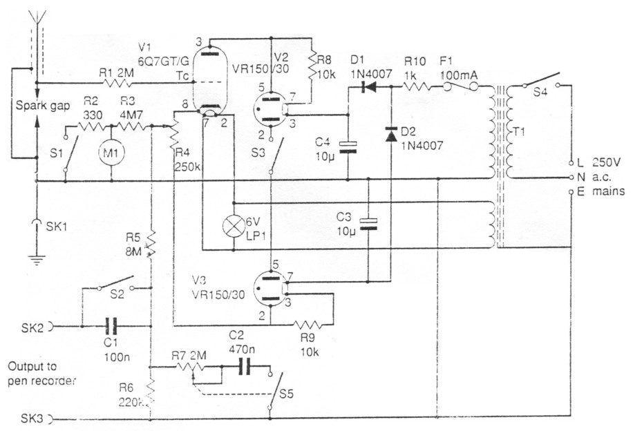
Fig. 1: Circuit diagram of electrometer
Transformer T1 has two secondary windings. a 250V which supplies the h.t. and a 6.3V used to power the heater of V1. Two silicon diodes D1 and D2 are connected as half-wave rectifiers across the h.t. winding of T1, providing both positive and negative rails. Two gas-filled stabilisers. V2 and V3 (VR150/30). are fed from the two half-wave rectifier networks, D1/C4 and D2/C3. providing 150V positive and negative supply rails. A stabilised supply is not essential, but does improve the small-signal sensitivit) and accuracy.
Other power supply arrangements could be tried if a surplus transformer is to hand, such as the type that can be salvaged from an old valved radio. These generally have a 300-0-300V h.t. winding plus one or two heater windings. This higher h.t. voltage is permissible provided the heater-cathode insulation of the valve used is adequate and the heater circuit is left floating. A 300-0-300V supply is about the maximum that most ordinary valves and bases will take without the risk of insulation failure. In addition, with more than 600V across the valve, the small-signal background noise level will rise due to supply variations and the internal leakage of the valve.
The valve is wired with a cathode load resistor chosen to set the current at full positive input of 1-2mA. The cathode voltage, and hence the antenna charge. is read by a centre-zero microammeter arranged as a voltmeter. scaled to suit the power supply voltage. The author used a 250kΩ potentiometer as the cathode resistor so that zero could be set with the grid of V1 earthed. Switch S I is used to select the 200V range resistor R3. by disconnecting the 20V range shunt resistor R2.
Switch S3 is included to give the instrument the option of an extra high voltage range. Another worthwhile refinement was to provide an output attenuator giving a 5V p/p signal for driving a pen recorder. The attenuator also includes an additional variable CR damping or integrating circuit for trace averaging, as well as a switched series capacitor to give an a.c. output signal for lightning transient recording.
Construction and components
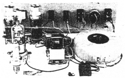
Both the instruments made by PW, and the author's prototype were constructed using the old bread-boarding technique. There are two good reasons for this, the first being that the design, as it stands, might be termed as a semi-experimental instrument. The shape and form of the instrument will depend on each individual's. requirements and component sources. The second reason for the rather exposed layout is partly due to the sensitivity of the instrument being disturbed by earth loops. This means that the use of a metal case is rather difficult and the use of a plastics or a wooden case is not advisable due to their potential fire risk.
Good quality new components for use in valved equipment are rather difficult to come by. particularly high voltage working electrolytic capacitors. However, there is plenty of leeway, within reasonable limits. on most of the values of capacitors and even resistors, but the component working voltages must be adhered to. A good source of these components may be your local radio and TV repair shop, they do still exist! All of the valves used are still available from a number of component suppliers. a short list of which appear in the "Buying Guide".
The centre-zero meter used in the PW prototype is not as sensitive as that used in the author's original, the choice being limited by availability and price of components. The 50-0-50µA originally used often went full scale, so it shows there is some room for improvement. The values of resistance shown will support most moving coil meters up to 250µA f.s.d. If after a period of use with a less sensitive meter it seems the usable scale is rather small. try experimenting with the values of R3 and R4.
Installation
When the readout is by moving coil meter and a servo-pen recorder with a sharp frequency cut-off above 10Hz, the induced 50Hz mains wave riding on the antenna is integrated to zero and ignored. although it may be many volts peak to peak. This "invisible" waveform will cause problems if the output is measured by d.v.m. or any instrument using switched sampling, and will have to be removed by additional signal conditioning, particularly if the electrometer output is to be recorded on computer.
A cathode follower valve has ideal characteristics for electrical field monitoring. Although the normal "fair-weather" field potential is some +100V/m from earth, the source impedance is so high that a 15m long antenna 3m above ground gives a cathode follower d.c. output signal of less than 10V positive, from a true ionic potential of nearly 1 kV. This inherent signal compression is useful, as the study of electric field is more concerned with change rather than actual potential. However, the equipment is still sensitive enough to permit the recording of small field changes as well as the more dramatic events associated with convective cloud building, thunderstorms and solar flares.
Antenna
Although an ordinary well-insulated wire antenna works well in dry weather, sensitivity falls dramatically when it gets wet. This is no bad thing in thunderstorms, but if true all-weather_ insulation is wanted. then additional insulators designed to preserve a dry surface must be used. One simple method is to provide a rain hood made from either plastics drain pipe with the insulator secured with resin up inside the tube, or to use the top half of a washing-up liquid bottle to shield the insulator (Fig. 2). Lastly, experience showed that the readings were less prone to variations caused by bodily movement near the instrument, if the antenna was brought into the shack via good quality coaxial cable (UR67).
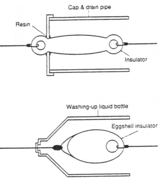
Fig. 2: Insulators with d.i.y. rain guards. Note that a higher insulation factor can be gained by adding further insulators
Lightning Spikes
Although the valve will tolerate high voltage lightning spikes, the antenna can still take a charge of several kV, so some precautions are advisable. It is a moot point whether it is safer to earth an antenna during a storm, or to fit a spark gap to earth it where the system enters the building. (On the PW prototype a small. stand-off insulator was not available to terminate the antenna to R1, so a new, but surplus, petrol engine spark plug was used. It was mounted on the base-board by a Terry clip bolted to a right-angle bracket. If the spark plug's outer metal case is earthed through the clip, it will serve not only as a cheap stand-off insulator but also double as a spark-gap. - Ed.) Lightning tends to strike the highest earthed object, and earthing the antenna may turn it into a more attractive target than nearby trees, power lines or TV antennas.
If lightning does strike, anything connected to outdoor wiring is at risk. no matter how remotely connected. including radios. TVs and phones. Even if it appears to be a relatively poor path to earth it will be at risk. Remember the most likely outcome of a lightning strike is fire, fortunately this type of thing doesn't happen all that often, but be sure to keep clear of the antenna when the sparks start to fly!
As a point of safety it may be wise not to rely just on the mains earth to ground the OV line of the instrument, a second local earth should be provided if possible, by some stout wire and an earthing spike driven into moist ground.
Results and research
The fact is, if you shut down the station while the storm is overhead, you will not miss much, because the field variations will be way beyond the range of the instrument. I find the most interesting recordings come from approaching and receding storms. where the field changes are attenuated by distance and become more readable. Individual lightning strokes can be recorded up to 80km away, and changes in amplitude and frequency give excellent early warning of an approaching storm. It is also possible to detect whether an approaching squall contains lightning, and by its decreasing stroke frequency, to see when lightning activity ceases in a dying storm.
Monitoring the electric field can be both fascinating and useful. The atmospheric potential varies with humidity, temperature. solar activity and convective cloud formation.
In summer. the "fair-weather" field reaches a peak in mid afternoon unless shower clouds develop. Large cumulus clouds passing over the antenna cause fluctuations and polarity reversals. which grow as shower clouds form. Distant lightning shows as sharp spikes on the trace, with amplitude increasing as the storm approaches.
Apart from forecasting thunderstorms, variations in background field foretell the approach of rain or other changes in the weather. A steady fall in potential several hours ahead of the normal daily cycle signals rain, and on a dull day. a further sharp fall in an already low voltage warns that rain is imminent. A steady rise in potential during drizzle or fog means better weather, and in winter, erratic "noise" accompanied by heavy cloud and falling potential forecast snow.
At night the field potential falls to a low level, unless thunderstorms threaten. Under these quiet conditions a trace at high gain will show occasional disturbances caused by solar events or ionospheric ripples caused by meteors burning up overhead. Another powerful source of disturbance is smoke. A nearby bonfire, or traffic exhaust can cause large erratic swings in the 1-10V range and give the impression of local instability associated with convection cloud building.
The electrometer also seems capable of registering seismic disturbances such as earthquakes and underground nuclear tests, both of these events having been monitored at the author's QTH. The exact mechanism by which the effects can be monitored is relatively complex, however, such changes in potential can be likened to those caused by distorting a piezoelectric substance.
Once installed, an antenna electrometer will give a fascinating insight into the complex electrical interchange between the ionosphere and the surface of our planet. The major power source of this phenomenon is the avalanche of charged particles from the sun. Who knows, this may be yet another instrument by which those cherished DX windows may be forecast!
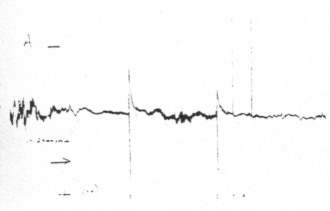
Fig. 3: Trace from author's electrometer shows two thunderstorm centres. Strikes 1 and 2 are about 24/32km away and show distances affect overshoot, while 3 and 4 are about 16km away and are of an unusual negative polarity. The spikes are clipped at 25V, although they peak at well over 100V
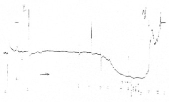
Fig. 4: Trace shows the passing of a positive charge centre overhead accompanied by heavily attenuated lightning spikes. The trace shows the characteristic voltage swing which often accompanies the onset of rain. Again the change is unusual, being from 250V positive to 250V negative in less than a second as a cloudburst started
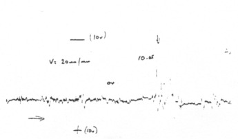
Fig. 5: Trace shows smoke effect on a typical summer morning trace, the background being about 4V positive
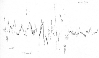
Fig. 6: Trace showing Perseid meteor shower on the morning of August 12, the f.s.d. being 250mV, and shows a nice shower around 0735 hours. Meteor contacts with the atmosphere show a very definite pos/neg pulse almost sinusoidal in nature. The very large off-scale pulses are caused by low flying aircraft, which as you can see, carry a large static potential
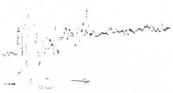
Fig. 7: This trace is thought to have been caused by a small earthquake in California!
Shopping list
| Resistors | ||
|---|---|---|
| 1W 5% Carbon film | ||
| 330Ω | 1 | R2 |
| 10kΩ | 2 | R8,9 |
| 220kΩ | 1 | R6 |
| 2.2MΩ | 1 | R1 |
| 4.7MΩ | 1 | R3 |
| 8.2MΩ | 1 | R5 |
| 4W Wirewound | ||
| 1kΩ | 1 | R10 |
| Potentiometer Linear | ||
| 250kΩ | 1 | R4 |
| 2.2MΩ | 1 | R7 with single pole switch |
| Capacitors | ||
| Polyester 400V | ||
| 0.1µF | 1 | C1 |
| 0.47µF | 1 | C2 |
| Electrolytic 500V | ||
| 10µF | 2 | C3,4 |
| Semiconductors Diodes | ||
| 1N4007 | 2 | D1,2 |
| Valves | ||
| 6Q7GT/G | 1 | V1 |
| VR 150/30 | 2 | V2,3 |
| Miscellaneous | ||
| T1 250V 100mA, 6.3V 500mA or similar | ||
| 250V 1A toggle switches S1-4 | ||
| International Octal valve holders (3) | ||
| 6V panel lamp with holder and bezel | ||
| M1 see text | ||
| SK 1-3 4mm type with matching plugs | ||
| F1 1¼in fuse with chassis mount holder | ||
| Plywood off-cut (baseboard) | ||
| Single gap spark plug (must be unused) | ||
| Hook-up wire | ||
| Terry clip | ||
| Knobs | ||
| Tag strip | ||
| Assorted hardware | ||
Tony Hopwood