A Two-tone Oscillator
Test equipment - Backbone of amateur radio
In this second part of his article on transmitter testing using a two-tone signal, Roger Alban GW3SPA describes the design process for the Wien Bridge oscillator and the low-pass filters, and concludes with a descrintinn of the complete unit.
The Wien Bridge Oscillator
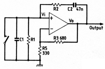
Fig 2.1
One of the simplest audio oscillators to construct is the Wien bridge oscillator. It consists of a series CR circuit in one branch of the bridge and a parallel CR circuit in another branch. In the oscillator circuit shown in Fig. 2.1, these components are R1, R2, C1 and C2. The circuit will oscillate at a frequency of Fo when the phase of Vi is identical to the phase of Vo. The frequency of F. in terms of the circuit component values is given by:
![]()
If R1 is equal in value to R2 and C1 is equal in value to C2, then:
![]()
If C is made to he a preferred value such as a 0.047µF (47nF), then the value of R will be given by:
![]()
For the oscillator to produce a 700Hz sinewave, the value of R will be:
![]()
Using preferred value resistors, the value of R can be obtained by placing in series a 4.7kΩ resistor and a 100Ω resistor.
For the oscillator to produce a 1900Hz tone, the value of R will be:
![]()
Careful selection of the 1.8kΩ resistors will result in the Wien bridge oscillator operating at 1900Hz.
Oscillation cannot he sustained unless the positive feedback through R2, C1 and C2 is equal to the forward gain controlled by R3 and R5. The gain through the Wien bridge at the frequency of oscillation Fo is:
![]()
If R1 = R2, and C1 = C2, then:
![]()
The forward gain of the operational amplifier at d.c. is:
![]()
If Adc is greater than 3, then the output waveform of the oscillator will not be a sinewave. It is therefore essential to select a suitable 680Ω resistor to produce a nice sinewave output.
Low-pass Filter
The waveform produced by the Wien bridge oscillator will contain a percentage of distortion. The two-tone test is dependent for accurate results upon the two tones being pure sinewaves. The distorted waveform produced by the Wien bridge oscillator is made up of a large number of harmonically related waveforms. If the output from the oscillator is fed into a low-pass filter whose cut-off frequency is just above the operating frequency of the oscillator, then it is possible to remove the harmonically related waveforms to end up with the fundamental waveform which will be a pure sinewave. To make a low-pass filter out of passive components would result in a rather large, bulky filter. However, it is possible to enlist the advantages of an operational amplifier to produce an active low-pass filter which gives unity gain. There is no lack of active low-pass filter designs to be found in many books in the subject. The problem is choosing a design that allows the filter to be designed in a short period of time without going through many different equations. The design must also contain good feedback stability, and must be constructed using the minimum number of components. The shape of the filter response is also important if the unwanted frequencies are to be removed from the wanted audio tone. The frequency response for three typical third-order filter circuits is shown in Fig. 2.2. The slope of the three filters rolls off at 60dB per decade. The author chose the 3dB Chebyshev design because of its sharp cut-off frequency. The circuit diagram of a single third-order low-pass filter with unity gain is shown in Fig. 2.3.
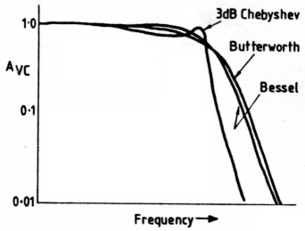
Fig 2.2
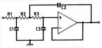
Fig 2.3
Design Procedure
There are at least two simplified design approaches that are possible to calculate the component values for the third-order low-pass filter. One method is to assume that:
R = R1 = R2 = R3
Solve the equation for R using pre-determined values of capacitance. The other method is to let
C = C1 = C2 = C3
and solve for C using pre-determined values of R. The author has found that the first method is quite simple and straightforward.
The unsealed capacitance values for the circuit shown in Fig. 2.3 for a 1dB peak Chebyshev filter are as follows:
C1" = 2.567 C"2 = 16.18 C"3 = 0.06428
The next step is to choose the corner frequency Flp required for the cut-off frequency and perform the following frequency scaling:
![]()
Next, choose a suitable value of R = R1 = R2 = R3 which will produce convenient values for C1, C2 and C3 according to the following equations:
![]()
The above equations assume that the gain of the operational amplifier is greater than 100 at the chosen corner frequency.
Practical Circuit
If we use a 741 operational amplifier, the gain of the amplifer at the oscillator operating frequencies will exceed the gain requirements of the design criterion. The cut-off frequency or corner frequency, FIp, will require to be set higher than the operating frequency of the oscillator.
For example, set the corner frequency say 30Hz higher than the frequency of oscillation. The filter which follows the 700Hz oscillator will have a corner frequency of 730Hz. We now have sufficient information to be able to calculate the component values and complete the design.
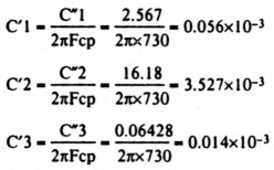
To obtain convenient values of capacitance, let us make R = R1 = R2 = R3 equal to 100kΩ, then:
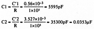
![]()
For practical reasons, C1 was made to be 5400pF (5.4nF) by shunting three capacitors together. A 2200pF was connected in parallel with another 2200pF, which in turn was connected in parallel with a 1000pF capacitor. In a similar way, C2 was made to be 0.034µF by shunting a 0.033µF capacitor with a 1000pF. For C3, the nearest preferred value of 150pF was used.
The corner frequency for the low-pass filter which follows the 1900Hz oscillator was made to be 2000Hz.
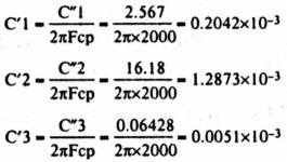
To obtain reasonable values of C, the value of R was made to be 100kΩ. Then:
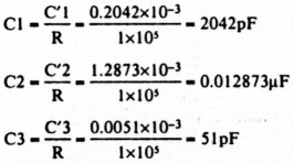
For practical reasons, C1 was made up by connecting two 1000pF capacitors in parallel, whilst C2 was made to be 0.0122µF by connecting in parallel a 0.01µF capacitor and a 2200pF capacitor. For C3, the nearest preferred value of 47pF was used.
The resulting sinewaves obtained at the outputs of the two active low-pass filters are combined using a 741 operational amplifier configured as a variable gain audio mixer.
Complete Circuit
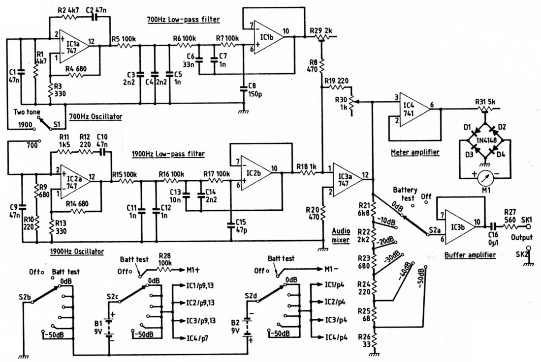
The complete circuit of the instrument is showin in Fig. 2.4. Either audio oscillator can be stopped from oscillating by grounding the non-inverting (+) input line to the operational amplifier. The output from the 730Hz low-pass filter (IC 1 b) is taken via a 2kΩ pre-set' to ensure that the audio levels from the two oscillators arriving at the inverting input of the variable gain audio mixer (IC3a) are the same.
The gain of the audio mixer is varied by a 1 kΩ linear potentiometer which is a front-panel control. The output from the audio mixer is fed to a 10dB step attenuator. It is assumed that the input impedance of the unity gain buffer (IC3b) is high. The design of the step attenuator uses preferred values of resistance such that the total resistance of the resistor chain (R21-R26) will be 10 001 ohms. The voltage drop across the 33Ω resistor R26 will be:
Therefore the voltage attenuation will be:
![]()
The same exercise can be repeated for the voltage drop across the 68Ω resistor in series with the 33Ω resistor, and the attenuation figure obtained will be 39.91dB. Try the calculation for the other attenuator step values for yourself.
The output impedance of the unity gain buffer amplifier is quite low. It is common practice to make the output impedance of the audio oscillator around 600Ω. It will therefore be necessary to place a 560Ω resistor, the nearest preferred value to 600Ω, in series with the output of the unity gain buffer amplifier.
You may recall that one of the aims was to build a piece of test equipment inside a scrap mobile CB set. This set, like most others, had a front panel meter which was used to measure output power and signal strength. The author decided to make use of this meter to monitor the ouput level applied to the 10dB step attenuator. Another unity gain buffer utilising a 741 operational amplifier was employed. The input of this amplifier (IC4) is connected to the output of the audio mixer. The output of the buffer amplifier is fed via a 5kΩ pre-set to a bridge rectifier employing 1N4001 or equivalent low-current diodes. The output from the bridge rectifier is connected directly to the meter.
The meter used in the vast majority of CB sets is the miniature edge type. The scale calibration will require to be amended. The author carefully removed the clear plastics top which exposed the strip carrying the artwork for the meter scale. This strip was removed and wiped clean using a small piece of cloth soaked in nail-varnish remover. A new scale was added using rub-down transfers after the strip had been painted white using a car touchup aerosol spray. The shape of the scale calibration will depend on the meter used. It is best calibrated in volts peakto-peak, with 20V at full scale. A battery-check mark should be added at the 18V point on the scale.
| Resistors 0.125W 1% metal film | ||
|---|---|---|
| 33Ω | 1 | R26 |
| 68Ω | 1 | R25 |
| 220Ω | 4 | R10,12,19,24 |
| 330Ω | 2 | R3,13 |
| 470Ω | 2 | R8,20 |
| 560Ω | 1 | R27 |
| 680Ω | 3 | R4,14,23 |
| 1kΩ | 1 | R18 |
| 1.5kΩ | 2 | R9,11 |
| 2.2kΩ | 1 | R22 |
| 4.7kΩ | 2 | R1,2 |
| 6.8kΩ | 1 | R21 |
| 100kΩ | 7 | R5-7,15-17,28 |
| Horizontal Cermet trimmers round type | ||
| 2kΩ | 1 | R29 |
| 5kΩ | 1 | R31 |
| Potentiometer linear | ||
| 1kΩ | 1 | R30 |
| Capacitors Ceramic plate | ||
| 47pF | 1 | C15 |
| 150pF | 1 | C8 |
| 1 nF | 4 | C5,7,11,12 |
| 2.2nF | 3 | C3,4,14 |
| Metallised polyester film 400V d.c. | ||
| 10nF | 1 | C13 |
| 33nF | 1 | C6 |
| 47nF | 4 | C1,2,9,10 |
| 0.1µF | 1 | C16 |
| Semiconductors diodes | ||
| 1N4148 | 4 | D1-4 |
| legrated circuits | ||
| 741 | 1 | IC4 |
| 747 | 3 | IC 1-3 |
| Miscellaneous | ||
| 100µA f.s.d. miniature edge meter | 1 | M1 |
| 4mm insulated terminals | 2 | SK1 |
| Rotary switch | 1 p. 3w | S1 |
| Rotary switch | 4 p. 8w | S2 |
| two-part aluminium project box | ||
| 6-F22 (PP3) battery clips | 2 | |
| 9 V batteries | 2 | B1, 2 |
| p.c.b. | ||
| nobs | 3 | |
| p.c.b. fixers | 4 | |
| connecting wire | ||
Construction
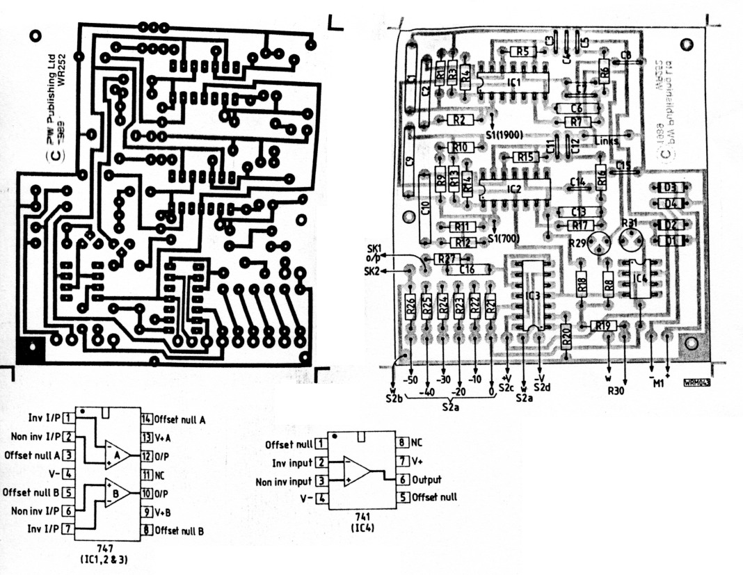
The prototype circuit was constructed on Veroboard, as shown on the front cover of April PW, but has been redrawn as a printed circuit board as shown in Fig. 2.5. The operational amplifier integrated circuits are mounted in sockets to ease construction and any subsequent fault-finding which may prove necessary. The wiring, layout and voltage checks should be carried out prior to installing the i.c.s.
The scrap CB set being used to house the instrument was completely gutted of all components and a 122mm square aluminium plate fitted in place of the original p.c.b. Onto this plate was bolted the new p.c.b. and the two PP9 battery holders as shown in the photograph. A second aluminium plate measuring 48mm by 123mm was attached by two bolts to the inside of the back panel to hide the holes left after removing the power and antenna sockets.
The front panel was redesigned by inserting a 50mm by 127mm aluminium plate into the front plastics cover. The square hole required for the panel meter, holes for the control knobs and output terminals can be scribed onto the aluminium plate by following the outline of the holes in the plastics front panel using a sharp pencil. The three-way rotary switch used to select the operation of the internal audio oscillators was fitted just above the output terminals by enlarging a hole formerly occupied by the radio/PA slide-switch. The variable output level potentiometer was located on the front panel in place of the microphone socket. That hole was too large in diameter to mount a standard potentiometer, and therefore two large washers were manufactured out of thin-gauge aluminium sheet to obtain a grip of the plastics front panel.
The holes to accept the control shafts were drilled in the aluminium front panel and it was then painted white using a car touch-up aerosol. The paint was allowed to dry hard over several days and the front panel sign-written using rub-down lettering transfers, sealed and protected with a layer of clear lacquer spray. Whilst waiting for the lacquer to dry hard, all the front panel controls may be attached to the original plastics front panel. Finally, using a contact adhesive, glue the aluminium front panel onto the front of the old plastics front panel. Cut the control shafts to the required length to take the control knobs using a small hacksaw. The two output terminals are attached directly to the aluminium front panel. Solder the connecting wires between the p.c.b. and the front panel controls.
First Checks
To correctly set up the two-tone oscillator you will need a calibrated oscilloscope which will be connected to the output terminals. Before inserting the operational amplifier integrated circuits into their sockets, connect the two 9 volt batteries and check the battery test facility for a reasonable needle deflection on the front panel meter. With the output level control in the -50dB position, check for the correct voltages on all i.c. sockets.
If you are satisfied that all the wiring is correct, switch off and insert the integrated circuits into their respective sockets, checking that you have them the right way round.
Calibration
Turn the variable level control fully clockwise and connect the oscilloscope to the output terminals. Switch the Select Oscillator control to 1900Hz and switch the output level control to OdB. Measure the amplitude of the output signal using the oscilloscope and adjust the meter amplifier Ail pre-set to obtain the correct meter reading. Now check the frequency of oscillation by observing the periodic time of the resulting output waveform. For 1900Hz, the periodic time for one complete cycle should be approximately 0.53 milliseconds. Check also that the periodic times of each half-cycle are equal. If the periodic time is incorrect, you will need to change the values of C and R in the oscillator circuit. Remember that you are not using close tolerance components. Exchanging the 0.047µF (47nF) tuning capacitors for others of the same marked value will possibly cause the frequency of oscillation to change because of the tolerance of the capacitors. The author used miniature metallised film capacitors which have a tolerance of plus or minus 20 per cent.
Next, switch the Select Oscillator control to 700Hz and adjust the 2kΩ balance pre-set to obtain the same peak-to-peak amplitude on the oscilloscope display as given by the 1900Hz oscillator. Check the frequency of the oscillator by measuring the periodic time of the waveform, which should be approximately 1.4 milliseconds. Also check the symmetry of the waveform. If the frequency needs to be adjusted, again exchange the 0.047µF tuning capacitors to obtain the correct periodic time.
Now switch the Select Oscillator control to two-tone and observe the oscilloscope trace. You should see that both the 1900Hz and 700Hz oscillators are operating, producing a continuous interfering pattern. Next, switch the 10dB attenuator from 0dB to -10dB, and observe the reduction in amplitude of the output signal. Continue to rotate the step attenuator and observe the continuing reduction of the output level. Check that in the Battery Test and Off positions, there is no output signal, thus ensuring that the wiring is correct and that the batteries will not be discharged when the instrument is switched off. The unit should now be fully calibrated and ready for use.
Conclusions
In its short working life, the two-tone tester has proved its worth within the radio shack. A multi-mode CB rig converted by the author for use on 10m was checked, and it was found that the power amplifier bias control needed to be adjusted to produce the desired linear output. The author also discovered that a number of transistor CB linears retuned to operate on 10m were anything but linear! The situation was improved by reducing the input level to the linear amplifier. In fact, the author modified the design of the linear amplifier to produce a linear output when being driven by a converted CB set. The two-tone tester has also found use within the radio shack as a general-purpose audio test oscillator.
I wish you all the best with this construction project, and look forward to hearing your linear signal on the air.
GW3SPA, Roger Alban.