Designing passive attenuator networks
Passive attenuators have many uses in all aspects of rf technology, matching and padding levels and impedances over wide frequency ranges. The following article by S. Niewiadomski explains how to design these networks with a bias towards their use in receivers.
Switchable sets of attenuators are often found in the front ends of modem synthesised receivers. The use of broadband, rather than narrowband, front end filters in these receivers often results in considerable amount of unwanted r.f. energy reaching the first signal stage and mixer, giving rise to overload problems.
One method of reducing this type of problem is to provide the option of adding some attenuation in the signal path. This can be effective in improving reception both when the desired signal is strong and is causing overload effects, or when a strong undesired signal is masking a weaker signal.
When faced with the task of including a measure of variable attenuation in the front end of a receiver being designed, or devising a method of attenuation the input to an existing receiver, probably the simplest method is to place a potentiometer between the antenna and the front end filters. This control is then adjusted to "pot down" the input signal by a variable amount depending on the severity of overloading.
Disadvantages
The use of potentiometers as variable attenuators present two disadvantages. First, the results are unpredictable which makes calibration difficult and secondly, the front end filters are likely to see different drive impedances depending on the setting of the potentiometer. In effect, if the filters are presented with the wrong drive impedance they will not achieve their design performance.
These problems can be overcome by providing a range of constant impedance attenuate networks which are switch into circuit as required. This arrangement not only gives calibrated attention, but also the correct and constant matching impedance for the front end filters.
Designing Networks
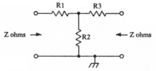
Fig 1.
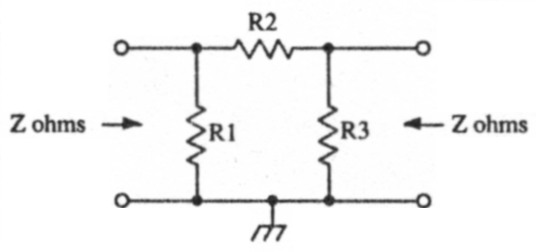
Fig 2.
Two simple configurations are available for unbalanced attenuators, that is, one side of the attenuator network is connected to ground. Both configuration, T and Pi-networks are shown in Fig. 1 and 2 respectively. These networks are symmetrical, in that they present the same impedance at their input and output terminals. For T-networks, the values of the resistors are given by the following equations;
![]()
![]()
Where:
Z is the input/output impedance of the network.
k is the desired attenuation, expressed as a ratio.
For the Pi-network, the values of the resistors elements are given by the following equations;
![]()
![]()
The attenuation required from a network is normally expressed in dB and the value of k for use in the above equation can be calculated by the following:
![]()
Component values for several typical networks are shown in tables 1 and 2. Attenuation levels from 5dB to 40dB (in steps of 5dB) for impedances of 50, 75 and 450Ω are catered for. Other level of attenuation can be worked out from the formula already given. As well as the exact resistor values, rounded values are also given.
In practice, the rounding of these values takes very little difference to the performance of the attenuators.
| Attenuation (dB) | 50Ω | 75Ω | 450Ω | |||||||||
|---|---|---|---|---|---|---|---|---|---|---|---|---|
| R1, R3 | R2 | R1, R3 | R2 | R1, R3 | R2 | |||||||
| exact | rounded | exact | rounded | exact | rounded | exact | rounded | exact | rounded | exact | rounded | |
| 5 | 14.0 | 15 | 82.2 | 82 | 21.0 | 22 | 123 | 120 | 126 | 120 | 740 | 680 |
| 10 | 26.0 | 27 | 35.1 | 33 | 39.0 | 39 | 52.7 | 56 | 234 | 220 | 316 | 330 |
| 15 | 34.9 | 33 | 18.4 | 18 | 52.4 | 56 | 27.5 | 27 | 314 | 330 | 165 | 150 |
| 20 | 40.9 | 39 | 10.1 | 10 | 61.4 | 56 | 15.2 | 15 | 368 | 390 | 90.9 | 82 |
| 25 | 44.7 | 47 | 5.64 | 5.6 | 67.0 | 68 | 8.46 | 8.2 | 402 | 390 | 50.8 | 47 |
| 30 | 46.9 | 47 | 3.17 | 3.3 | 70.4 | 68 | 4.74 | 4.7 | 422 | 390 | 28.5 | 27 |
| 35 | 48.3 | 47 | 1.78 | 1.8 | 72.4 | 68 | 2.67 | 2.7 | 434 | 470 | 16.0 | 15 |
| 40 | 49.0 | 47 | 1.00 | 1.0 | 73.5 | 68 | 1.50 | 1.5 | 441 | 470 | 9.0 | 8.2 |
| Attenuation (dB) | 50Ω | 75Ω | 450Ω | |||||||||
|---|---|---|---|---|---|---|---|---|---|---|---|---|
| R1, R3 | R2 | R1, R3 | R2 | R1, R3 | R2 | |||||||
| exact | rounded | exact | rounded | exact | rounded | exact | rounded | exact | rounded | exact | rounded | |
| 5 | 178 | 180 | 30.4 | 33 | 268 | 270 | 45.6 | 47 | 1606 | 1500 | 274 | 270 |
| 10 | 96.2 | 100 | 71.2 | 68 | 144 | 150 | 107 | 100 | 866 | 820 | 640 | 680 |
| 15 | 71.6 | 68 | 136 | 150 | 107 | 100 | 204 | 220 | 645 | 680 | 1225 | 1200 |
| 20 | 61.1 | 56 | 248 | 270 | 91.7 | 100 | 371 | 390 | 550 | 560 | 2228 | 2200 |
| 25 | 56 | 56 | 443 | 470 | 83.9 | 82 | 665 | 680 | 503 | 470 | 3988 | 3900 |
| 30 | 53.3 | 56 | 790 | 820 | 79.0 | 82 | 1185 | 1200 | 479 | 470 | 7108 | 6800 |
| 35 | 51.8 | 56 | 1405 | 1500 | 77.7 | 82 | 2108 | 2200 | 466 | 470 | 12649 | 12000 |
| 40 | 51.0 | 47 | 2500 | 2700 | 76.5 | 82 | 3750 | 3900 | 459 | 470 | 22498 | 22000 |
Incorporating the Networks
The choice of attenuator types is a matter of personal preference. A useful set of attenuation values to incorporate into a receiver front end would be 10, 20 and 30dB, with the option of switching the tenuators out of circuit altogether.
A typical configuration is shown in Fig. 3 for an amateur band receiver with a 50Ω input impedance. Here, three levels of attenuation (as well as 0dB) are selectable, and the narrowband filters are manually selectable. The r.f. amplifier can either be in or out of circuit, so that the front end gain configuration can be chosen to suit any set of listening conditions.
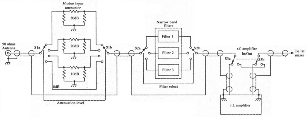
Fig 3.
Receiver Front-end
A general coverage receiver front end is shown in Fig. 4. The broadband filters are designed for a 450Ω impedance level, and therefore the attenuator networks have to be designed for this impedance. High impedance antennas are connected directly to the attenuator switch, whereas 50Ω antennas are matched to the 450Ω system via a broadband transformer giving a 9:1 impedance transformation.
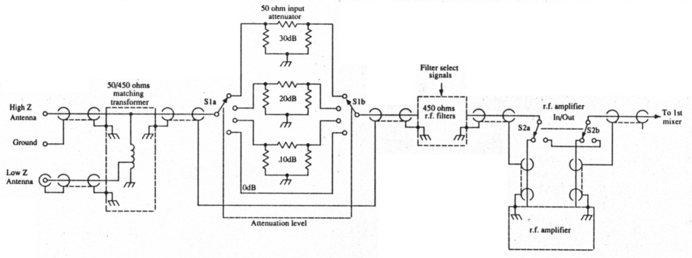
Fig 4.
Construction
It is hardly worthwhile building a p.c.b. containing the attenuator resistors and making connections to a front panel switch. It is much easier to mount the resistors directly on to the terminals of the attenuator switch itself.
The earthy ends of the attenuator network are best connected to the braid of the coaxial cable carrying the signal to and from the switch.
Balanced Networks
There is a family of attenuators where neither side of the network is connected to ground, and these are referred to as balanced networks. Balanced T and Pi-networks are shown in Figs. 5 and 6 respectively. Component values for these balanced networks can easily be derived from their unbalanced counterparts. The values of the resistors in the upper and lower branches are simply half the value of their equivalents in the unbalanced networks. The shunt resistors have the same value as before.
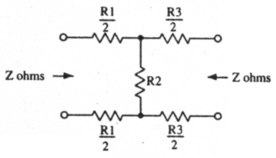
Fig 5.
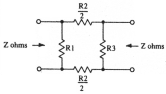
Fig 6.
Computer Generated Resistor Values
Resistor values for any impedance level and attenuation can be derived on a calculator using Equations 1-4, but if many networks are to be designed the process can be time-consuming and tedious.
However, the equations are ideally suited for programming into a home computer. The program contained in this article is written in ZX BASIC and carries out the calculations already discussed. Only simple statements have been used and the program can easily be converted to other versions of BASIC or even other languages.
The program starts by prompting the user for the impedance (in ohms) and the required attenuation (in dB). It then computes and outputs the T and Pi-network resistor values as both their exact and nearest E12 series rounded values.
Simplifying the Program
If some of these facilities are not required, blocks of the program may be omitted. For example, if the rounded resistor values and the exact attenuation they produce are not required, then lines 3(X)-400, 600-700 and 2000-4070 can he omitted, considerably simplifying the program.
Source code
PROGRAM 1. T and pi network attenuator design program.

100	PAPER 7: BORDER 6: INK 0: CLS
110	PRINT: PRINT "Attenuator network calculation"
120	INK 2: INPUT "impedance level (ohms):";imped
130	INPUT "attenuation (dB):";atten
140	LET k = 10^(-atten/20)
200	REM T network calculation
210	LET ri = imped*(1-k)/(l+k): LET r3 = rl
220	LET r2 = imped*2*k/(1-k^2)
240	PRINT: PRINT " T network exact values:"
260	PRINT "	R1,R3 = ";r1;" ohm"
270	PRINT "	R2 = ";r2;" ohm"
300	PRINT: PRINT " T network rounded values:"
320	LET res = rl: GOSUB 2000
340	LET rl = res: PRINT "	R1,R3	";res;" ohm"
360	LET res = r2: GOSUB 2000
380	LET r2 = res: PRINT "	R2	";res;" ohm"
400	LET r3 = rl: GOSUB 3000
500	REM pi network calculation
510	LET rl = 1mped*(1+k)/(1-k): LET r3 n rl
520	LET r2 = imped*(1-k^2)/(2*k)
540	PRINT: PRINT " pi network exact values:"
560	PRINT "	R1,R3 = ";r1;" ohm"
570	PRINT "	R2 = ";r2;" ohm"
600	PRINT: PRINT " pi network rounded values:"
620	LET res = rl: GOSUB 2000
640	LET rl = res: PRINT "	R1,R3 = ";res;" ohm"
660	LET res = r2: GOSUB 2000
680	LET r2 = res: PRINT "	R2 = ";res;" ohm"
700	LET r3 = rl: GOSUB 4000
1000	REM pause subroutine
1010	INK 0: PRINT: PRINT " Press any key to continue"
1030	PAUSE 0
1040	GO TO 100
2000	REM resistor rounding routine
2010	FOR n = 1 TO 8
2020	LET dec = 10^(n-2)
2030	FOR v = 1 TO 12
2040	READ a,b,c
2050	IF res < a*dec AND res >= b*dec THEN GO TO 2100
2060	DATA 1.1,0.91,1.0,1.35,1.141.2,1.65,1.35,1.5,2.0,1.65,
1.8,2.45,2.0,2.2,3.0,2.45,2.7,3.6,3.0,3.3,4.3,3.6,3.9,
5.15,4.3,4.7,6.2,5.15,5.6,7.5,6.2,6.8,9.1,7.5,8.2
2070	NEXT v
2080	RESTORE
2090	NEXT n
2100	LET res = c*dec
2110	RESTORE
2120	RETURN
3000	REM T network attenuation calculation subroutine
3010	LET rsum = r2+r3+imped: LET rx = r2*(r3+imped)/rsum
3030	LET vx = rx/(imped+rl+rx)
3040	LET vout = vx*imped/(r3+imped): GO TO 4050
4000	REM pi network attenuation calculation subroutine
4010	LET ra = imped*r3/(imped+r3): LET rx = rl*(r2+ra)/(rl+r2+ra)
4030	LET vx = rx/(imped+rx)
4040	LET vout = vx*ra/(r2+ra)
4050  LET attenuation = -(20*LOG(vout)/LOG(10)+6.02)
4060	PRINT " attenuation = ";attenuation;" dB"
4070  RETURN