High voltage regulated PSU
This project grew from three basic requirements. The first came from a need to regulate the unusual voltage required for a valved radio under repair. The second arose from a need to supply power to the PW Empire four valve QRP transceiver published in the 1000th issue of PW and finally, just to experiment with the idea of a high voltage transistor regulated p.s.u.
Beginnings
The original was used to power a valved receiver which had 'blown' both the original transformer and the (gas-filled) stabiliser valve. For those of you who have not met one of these, they are in effect a neon (and/or other rare-gas) filled valve, which acts in the same way as a Zener diode. The Zener diode shown (D5) in the circuit diagram could have admirably fulfilled this function, as the current requirement was small, about 5mA, in total.
Second task
The second requirement however, was somewhat more than the Zener diode would have been able to cope with. The PW 'Empire' required a maximum current of about 20-25mA under full loading. This would have required a Zener diode of at least 2W dissipation. So I felt some form of active regulator was a better option. A simple voltage buffer (emitter follower) circuit was tried, and rejected the first time I inadvertently shorted the output leads together. Both the transistor and the Zener diode mutually self-destructed and I felt rather foolish.
Clearly some form of current limit was required for the circuit, but a design in which the full rectified voltage could be applied across the regulating transistor without damaging it.
Reference level
The first two requirements, modified by the third, resulted in the circuit shown in the diagram Fig. 1. The Zener diode (D5), has been demoted to merely acting as a reference for the emitter of the difference amplifier TR1. By this means the emitter of TR1 is held at approximately 100V and a portion of the regulated output is fed to the base of this transistor, via limiting resistor R3. Transistor TR2 acts as an emitter follower to the corrected output voltage at the collector of TR1. Both of these transistors have to be able to withstand the whole of the rectified voltage, present across the reservoir capacitor C1. They are both high voltage types. Don't try to use any other types unless the devices you wish to substitute have a VcE of greater than 300V.
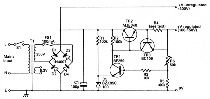
Fig. 1: The circuit diagram of the regulator, note the simplicity, the p.s.u. has only one capacitor.
Current limit
The current limiter transistor TR3 has no similar voltage limitations placed upon it and almost any small signal type could be used in its place. The maximum voltage across this is around 1.5V (just prior to limiting), and the maximum current carried would be about 3.5mA under total short circuit conditions.
As the total supply current flows through R4, the voltage across it will start to rise as the load current increases. At the point at which this voltage rises above 0.6V, TR3 comes into conduction, by-passing the base current of TR2 to the output connection. This continues to a point at which the base current of TR2 becomes fixed, allowing only a limited output current to flow.
Table 1 has list of values for R4 at various limiting current levels. I don't recommend that you have limiting currents in excess of 100mA, as 2530W may be dissipated by TR2 under short circuit conditions at those levels.
| Current limit | R4 value | Load resistor | Min. power rating |
|---|---|---|---|
| 5mA | 120Ω | 27kΩ | 1W |
| 10mA | 68Ω | 15kΩ | 1.5W |
| 15mA | 47Ω | 9.1kΩ | 2W |
| 20mA | 33Ω | 8.8kΩ | 2.5W |
| 25mA | 27Ω | 5.6kΩ | 4W |
| 50mA | 12Ω | 2.7kΩ | 7W |
| 75mA | 8.2Ω | 1.8kΩ | 10W |
| 100mA | 6.8Ω | 1.2kΩ | 15W |
Construction
It's advisable to build this project on the designed board available from the PW PCB service. The prototype however, was built on perforated matrix board which is just adequate for the purpose. A mistake at these voltages could be expensive (and possibly fatal). The on-board transistor, TR2 is mounted with the metal plate uppermost for heat-sinking purposes. You should take great care that the leads of the transistor don't touch the heatsink. You should also take great care, when the unit is in operation, to avoid touching the heatsink yourself, as it is at 300-350V potential.
Note: If the current limit is set at less than 50mA then only half of the heatsink area is required, but above this level all of the heatsink is needed.
Mount capacitor C1 last after double checking the placing and orientation of all other components. Double-check that capacitor C1 is also correctly placed and orientated. You should bear in mind that it could explode with some violence if wrongly connected.
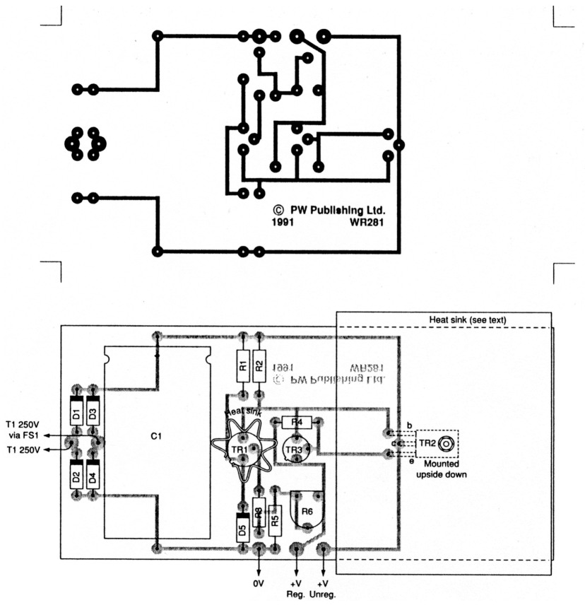
Fig. 2: The track pattern and overlay diagram of the regulator p.c.b.
Testing
If all is well set the preset resistor R6 to about mid-travel position and switch on. A voltage of about 350V should be present at the unregulated output and about 125V at the regulated output. If not, switch off and investigate. The regulated output should be variable between 100-150V aproximately.
Finally you should set the output to 125V. Using a suitable resistor, in both power handling and resistance value, load up the regulated output to just under the limiting value (Table 1 has values and power handling requirements of this resistor). The output should drop by only one volt or less. The p.s.u. is now ready for use in a suitable surrounding box or case.
Miscellaneous
Valve transformer (250/6.3V) Maplin type XP27E, p.c.b. (see PW services page),100mA fuse and holder, heat-sinks: Maplin type FL78K for TR1, type FL14U for TR2 (see text). An assortment of screws, washers and nuts to suit, a suitable earthed and/or insulated box to contain the unit, interconnecting wire of suitable high voltage grade. Capacitor C1 is available lin packs of five only) from RS Components or Electromail. You may be able to obtain one from your local electronics supplier by asking them to 'split' a pack, in return for a small surcharge on the price of a single item.
Maplin Electronics., P.O. Box 3, Rayleigh, Essex SS6 8LR. Electromail, P.O. Box 33, Corby, Northants NN17 9EL.