The PW Chatterbox
1.8MHz AM transmitter and receiver, part 2
In Part 2 of the two-unit 1.8MHz a.m. project, George Dobbs G3RJV describes the construction of the separate receiver section.
Before starting on the receiver side of the' Chatterbox', we ought to take a final look at the transmitter itself. The Chatterbox transmitter is built separately, because many constructors will want to use it in conjunction with an existing receiver on 1.8MHz.
It's been assumed that an existing antenna tuner and low-pass filter unit will be used with the transmitter. However, if you intend to use the complete transmitter and receiver combination as a 'stand alone' unit, it will be necessary to use a suitable low-pass filter to reduce potential harmonics.
A filter of this sort can be built into the transmitter, or it can be an outboard type used in conjunction with a small antenna tuner. What the individual constructor does of course, will depend on the size of casing and whether or not the project is built as separates or as one small unit.
With the change-over switching described in the previous article, the transmitter can be used with any 1.8MHz receiver. If you don't have a suitable set, you can add a simple single board receiver of the sort described here. However, bear in mind that the receiver is not a DX model and it's designed for using the Chatterbox combination in local a.m. nets.
The Receiver
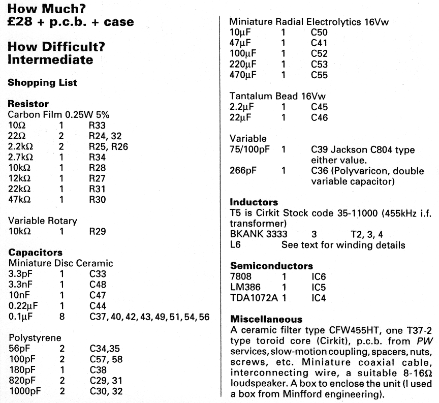
The receiver section is based on the TDA1072A a.m. receiver i.e. This is an inexpensive chip which performs all the functions of an a.m. receiver between the antenna and the audio stages.
The TDA1072A's sensitivity and signal handling capabilities are such that it's suitable for this application. The i.e. also supports several features not used in this design.
Some of the features are made available on the p.c.b., should you wish to incorporate them in the receiver. For example, the chip provides an S-meter output, a muting facility and a buffered oscillator output for driving a frequency counter. The circuit is shown in Fig. 2.1, and it closely follows the manufacturer's specification sheet.
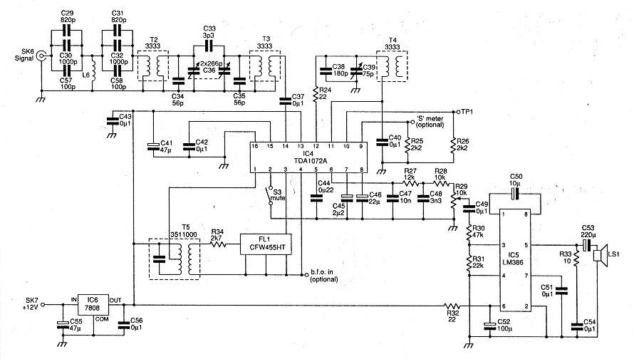
Fig. 2.1: The Chatterbox receiver circuit diagram.
The incoming signal is filtered with a high-passfilter, L6 (wound on a toroid) and associated capacitors, and a two stage band-pass filter, comprising of T2 and T3. The high-pass filter was included because the receiver operates close to the medium wave broadcasting band.
Winding the toroid for L6 is a simple job and it only requires a little concentration for a neat job. All you need to do is wind 24 turns of 0.4 or 0.5mm enamelled copper wire on a T37-2 core.
I have a local commercial broadcasting station at the top end of the medium waveband that can light bulbs in my location in Rochdale! The high-pass filter was included to kill the pop music breakthrough. The band-pass filter has manual tuning provided by a polyvaricon capacitor, C36, to peak the wanted band signals and reduce the out-of-band signals.
Receiver Tuning
The band is tuned using a variable capacitor, C39, in conjunction with T4. Although the TDA 1072A was designed for varicap tuning, this arrangement allows for very stable tuning over the band.
The variable capacitor, C39, is a standard value, 75pF, (a 100pF may be used as an alternative) which more than covers the whole band. This tuning capacitor is mounted directly on the printed circuit board.
The ground connection on C39, is made through the mounting nut to the p.c.b. To avoid any problems with poor connections, I also added a wire between the tag to the moving vanes and the ground plane on the top of the printed circuit board.
Intermediate Frequency
The i.f. at455kHz, is filtered by using a CFW455HT ceramic filter and an i.f. transformer, T5, placed between the mixer output, pin 1, and the i.f. amplifier, pins 3 and 4.
It's possible to inject a b.f.o. signal at pin 4, to make the receiver available for c.w. and s.s.b. reception. Several radio amateurs have used this i.e. to make a c.w. and s.s.b. receiver. I tried injecting a 455kHz signal at pin 4, but found that it triggered the internal a.g.c. This reduced the overall gain of the receiver, to what I considered to be an unacceptable level.
Sprat Debate
There was a debate between DF2OF and G8SEQ, reported in the G-QRP Club journal Sprat (issue 57), on using a b.f.o. with the TDA1072 without a.g.c. problems. The technique is obviously open to experimentation!
One possible idea, would be a b.f.o. which only injects a signal when netting the transmitter to the receiver. This technique would make the netting process somewhat easier.
The circuitry around pins 5 to 8, clearly demonstrates that the TDA 1072A requires considerable decoupling around the audio stages. Don't miss out these capacitors, as reducing the decoupling causes instability. To further help stability, the receiver is built on a double-sided p.c.b.
The audio amplifier is the popular LM386 i.c. in its high gain configuration. A muting switch can be applied to pin 2, but in this application the receiver is switched off during transmit cycles, so pin 2 is grounded. Switching off the receiver is quite acceptable in this particular application.
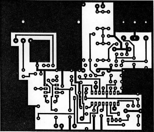
Fig. 2.2: The Chatterbox receiver p.c.b. copper track layout.
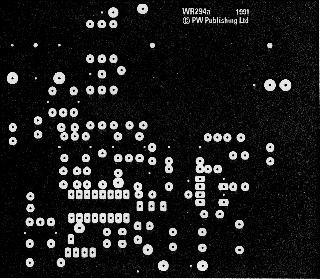
Fig. 2.3: Receiver ground plane details.
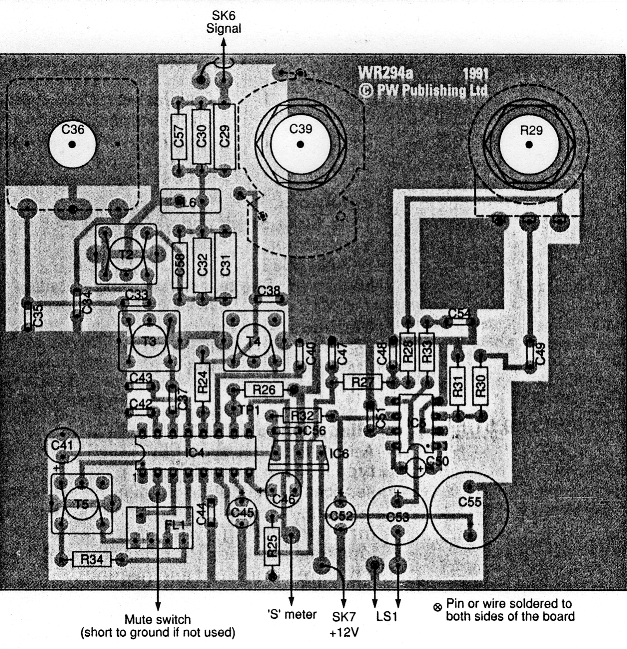
Fig. 2.4: The Chatterbox receiver component placing overlay diagram with off-board connections shown.
Building The Receiver
The receiver is built on a single p.c.b. which also holds the three controls, peak (C36), tune (C39) and audio volume (R29). The board is a double-sided p.c.b., the top of the board forming a ground plane. Wherever possible, the grounded connections and leads should also be connected to the top side of the board.
It can be helpful to build and test the audio stages first. This job would start from the loudspeaker output as far as pin 6 on the TDA1072A. The capacitors C45 and 46 are tantalum bead types to fit in the small space available. When the audio stages are wired, the rest of the components may be added.
Setting Up
The method used to set up the receiver will depend upon the available test equipment. Although some test equipment is helpful, the receiver can be set-up by using signals on the band.
Even after a setting-up operation on the test-bench, I tend to make final adjustments using signals on the band. The first task is to get C39 to tune over 1.8 to 2MHz. It is, of course, tuning 455k Hz lower than the range 1.8 to 2.0 MHz.
One suitable method is by using a frequency counter to take a signal from TPI. This is a simple technique, but some poorly buffered counters can change the frequency of the signal.
Another method is to listen for the signal on a receiver, set to receive c.w. or s.s.b. This is done by connecting a short wire antenna to the receiver, and then draping it close to C38. The adjustment is by means of the core in T4. You may find it necessary to increase the value of C38, by perhaps 56 or 68pF (the actual value depends on the individual coil) to achieve this easily.
Bandpass Adjustments
The adjustment of the band-pass filter is rather more exacting, and it's done by adjustment of T3 and T4. The ideal method is to set the two cores to peak the band in conjunction with C36.
This may be done by injecting a low level signal of the required frequency into the receiver input or using signals on the band. There are enough 'jingle-jangles' from navigational beacons on 1.8MHz to provide tuning signals. The signals to avoid are any popular songs creeping in from medium wave broadcasting stations!
Begin the process by setting C36 about midway, and injecting or finding a signal at around 1.9MHz. Next, T2/3 are adjusted to peak the required signal.
You should then set a signal at about 1.8MHz, rotate C36 to peak the signal, and then re-adjust T2/3. This operation should then be repeated at around 2MHz. It's worth repeating the whole tuning up process at least twice, and then perhaps re-peaking on a favoured frequency on the band. To finish the job off, you should peak T5, the i.f. transformer, for maximum signal.
The receiver input is designed for 50Ω, and it should be used into a correctly matched 50Ω input from an antenna or tuning unit. An antenna tuning unit will also help to reduce adjacent channel broadcast signals.
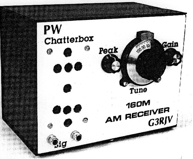
Boxing The Chatterbox
The receiver unit can be mounted in a box the same size as the transmitter. The interconnecting leads that form part of the transmit to receive switching, are clearly shown in the photographs.
To provide a suitable receiver tuning rate, a slowmotion drive is required for C39. I used an in-line epicyclic drive. To enable the slow-motion drive to be used, the receiver p.c.b. is mounted behind the front panel, using stand-off pillars spaced to suit the drive.
Switching Modification
As the unit uses a.m., and frequency stability is less critical, several short-cuts may be taken in the transmit-receive switching arrangements. For example, the v.f.o. is switched off during the receive periods, as the warm up' drift is insignificant in terms of an a.m. signal. For the same reasons, the receiver is completely switched off during transmit periods.
The circuit of the change-over arrangement was shown in Part 1 as Fig. 1.1. The switching circuitry now requires a small modification to incorporate the receiver half of the project.
The change-over action is centred around a 12V relay, RL1, (operated by) the p.t.t. switch on the microphone. This is a double-pole change-over relay which switches the antenna between the receiver andthe transmitter output.
An extra supply wire is added to the contacts on the switch. This supplies 12V to the transmitter and the v.f.o. The extra wire, from the normally closed contact, supplies the receiver with 12V which is disconnected when the p.t.t. is operated and the relay switches to transmit.
As the transmitter and receiver are separate units, the transmitter has to be `netted' to the receiver frequency. This is done by switching on the v.f.o., and then tuning it to the desired frequency on the receiver. The `Net' Switch, S2, connects a 12V supply directly to the v.f.o. when the unit's in the receive mode.
If the transmitter is to be used for c.w., a more sophisticated method of change-over will be required. In this case, the v.f.o. should be left to run all the time. Additionally, a method of off-setting its frequency is required during receive periods, to prevent it being picked up on the receiver.
Chattering In Morse
Although the Chatterbox was designed as an a.m. transmitter, it works very well on c.w. Colin Turner G3VTT, has built a prototype Chatterbox transmitter and uses it successfully on c.w. with the slight modifications shown in Fig. 2.5.
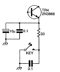
Fig. 2.5: The c.w. modification for the Chatterbox suggested by G3VTT.
The 2N3866 driver transistor is keyed, using the arrangement shown in the diagram. This produces pleasant keying characteristics.
With the key added, the microphone p.t.t. point still provides the change-over from transmit to receive. The microphone really needs to be unplugged when you're using c.w., but an extra switch can be added to the transmit section for change-over.
A better arrangement is to disable the modulator. Ideally, this is done by removing the supply to the 2030 audio integrated circuit and shorting out the modulation transformer, T1. The 12V supply then goes directly to the IRF510 p.a. stage. However, after telling you about the proper way to do it, I understand that Colin G3VTT, merely shorts out the modulation transformer!
I hope you build, and enjoy using this delightful little rig. There's quite a few of them about already. Perhaps your Chatterbox could be the next one on the air!