Making a valved active antenna
This receiving project uses a valve working with only 12V h.t. If you suffer from local TV timebase interference or computer hash, then it's worth a try. The project covers the frequency range 1 to 10MHz (30MHz with reduced gain).
The letters page in PW gave me a strong hint that quite a few radio enthusiasts are interested in valved circuits. However, the main difficulty seems to be with the high voltage supplies required.
The heater requirements, typically 6.3V at 0.3A, are a bit wasteful. But if the equipment is operated from mains or from a car battery, then it doesn't matter too much.
A surprising number of valves can be used at low h.t. voltages. Circuits such as audio oscillators and add-on b.f.o.s can often work with only a 12V anode supply.
Some years ago there were car radios using 12V h.t valves. I've recently become quite interested in applications where 12V serves as both the low tension or 1.t. heater supply and the high tension h.t. anode supply.
This little circuit uses the low voltage technique. Although it is not so good on the higher h.f bands, it's useful on 1.8, 3.5, and the 7MHz amateur bands and up to the 9MHz broadcast band.
Simple concept
You might be wondering what an active antenna is, and I have to admit that the term may mystify the uninitiated. Actually it's a very simple concept, so let's take a look at the circuit, in Fig. 1.
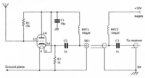
Fig. 1: Circuit of the valved active antenna, with the valve diagram and pin-out numbering shown in Fig. 4. The power supply insertion unit circuit is also shown (see text).
In practice, an 'active antenna' is a small antenna followed by an amplifier. Despite this, the active antenna does have some special properties, although there are pitfalls in its design. But they have something to offer the amateur (even those with large gardens).
First of all, we'll look at the 'small antenna'. And, for our purposes, I'll suppose this is a vertical whip 1m long. A whip antenna of this size will have sufficient pick-up at h.f., to have approximately 1µV of background noise at the base.
Most receivers can operate with an input of around 1µV, so there is no point using a larger receiving antenna. Or is there?
The main problem, is one of mismatch between the whip antenna and the receiver. The whip is roughly equivalent to a small capacitor of, let's say, 10pF.
At 1 MHz this represents a high impedance (or reactance) of about 16kΩ. If it's connected directly to a receiver having a 50Ω input impedance, most of the signal will be lost.
What's needed next, is some sort of matching device which will keep the 11.1V delivered by the antenna, and deliver it to 50Ω receiver input socket. This can be done using an amplifier having a very high input impedance, and low output impedance.
In the world of valves, the traditional circuit to match a high to a low impedance is called a cathode follower. Nowadays, it has a modern equivalent, in the emitter follower with bipolar transistors, and the source follower when f.e.t.s. are used.
Eliminate interference
By using a small whip antenna mounted well away from TV sets, dimmer switches, vacuum cleaners, computers etc., it's possible to eliminate much of the interference heard on the lower h.f. bands. The reduction can be dramatic.
It's most unusual to find a quiet 3.5MHz band at most amateur stations. This is because the large antenna used for transmitting, picks up all interference sources in the locality.
Additionally, the average antenna provides far more pick-up than a modern receiver needs. Once the atmospheric noise is audible, there's no point using a large antenna, as both noise and wanted signal increase together.
The active antenna, on the other hand, is physically small and in use is placed well away form interfering devices. In practice, this form of antenna is only just large enough so that atmospheric noise is audible. This level of input leaves the receiver lots of overload margin for stronger signals.
Problem feeder
There is one particular problem in the design of active antennas. It's that the feeder itself will pick up far more signal than the whip antenna itself, along with lots of interference.
The main unwanted pick-up of signals, tends to happen on the outer braid of the coaxial cable. So, because of this, it's necessary to avoid the feeder introducing signals into the whip.
Reducing the problem from the feeder, is done by providing a good ground plane made of wire netting or cooking foil. The diagram, Fig. 2, shows how to avoid the whip 'seeing' the feeder.
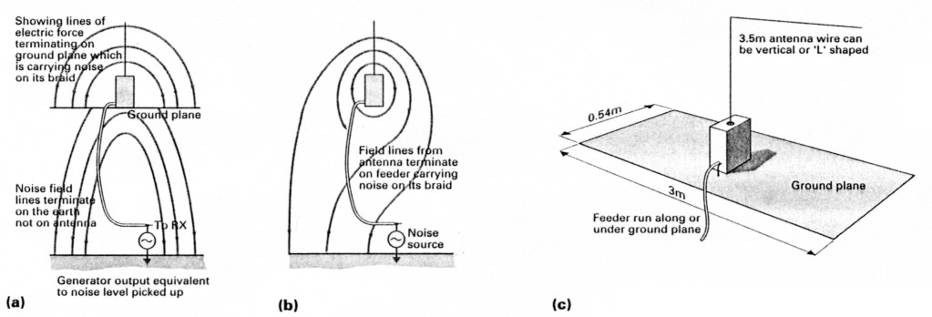
Fig. 2: (a,b and c) below: Diagrams illustrating screening effect of a ground plane, and why the coaxial cable needs to be screened from the active antenna. The author's practical, and proven ground plane is also shown with working dimensions (see text).
In engineering terms, we can say that the electric field lines from the whip antenna, must terminate on the ground plane and not the feeder. You may ask, why not use a dipole as the small pick-up antenna?
The difficulty of using a dipole, is that to avoid the interference on the feeder getting into the antenna, there would need to be perfect balance. Unfortunately, it's simply not possible to achieve the necessary degree of balance.
I'll suggest an example and say it was specified that an interference level of ImV on the feeder, should only gives lµV on the antenna. In practice, this requires 60dB of rejection, which is very hard to achieve.
At the higher end of the h.f. range, there are less advantages in using an active antenna. This is because the atmospheric noise level is lower.
So, at the higher h.f. frequencies, the amplifier could, with advantage, have a little more gain. Because of this, I would recommend the present design more for the lower frequency bands.
Small Box
The amplifier is built into a small metal box, large enough to accommodate the few components. The valve holder is mounted on a metal plate fitted across the box, although any type of construction will do.
The output connector is fitted to the lower side of the box, and the antenna wire is brought out through a large hole in the top. It's very important to a avoid capacitance between the antenna wire and earth, as this shunts the signal. I used a ceramic insulator at this point, but it's not really necessary.
The pin connections to the valve are shown in the inset, on the circuit diagram, Fig. 1. These are numbered looking from below the valve in a clockwise direction starting from the gap. This is opposite to modern i.c. pin-out numbering.
Suitable Valves
There are many suitable valves for this project. I used a 12AT7 (also called ECC81). This easily obtainable valve contains two triodes, in a single glass envelope.
To improve the performance, I connected the valves in parallel. However, the two heaters, which require 6.3V each, were connected in series to operate from a 12V supply.
The antenna itself is 3m of wire, which in my case, is tied to the rafters as an inverted 'L'. You can support the antenna vertically if you wish, by using a wooden pole or bamboo.
My ground plane was made from a roll of aluminium cooking foil measuring 3m by about 0.5m wide. This is ideal for loft installation. If the system is to be used outdoors, either a similarly sized piece of wire netting or a few wire radials would be more suitable.
Don't forget that the idea of the ground plane, is to screen the antenn.t from the feeder. So, if you're using the antenna outdoors, run the feeder along or under the ground in the vicinity of the active antenna itself.
The d.c. power is fed up the feeder to the amplifier, using r.f. chokes to separate it from the signal. This is the same technique used in masthead amplifiers, employed in TV applications.
As the consumption is about 300mA, it's necessary to keep the resistance of the chokes below about 30 total, to avoid an excessive voltage drop. However, this was more or less achieved with the prototype without any special precautions from me!
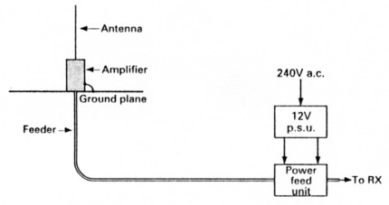
Fig. 3: Illustration showing complete system. The combined 12V h.t./l.t. power supply is fed to the amplifier from the power feed unit (circuit shown as inset in Fig. 1). See text for details on winding the low resistance r.f.c.
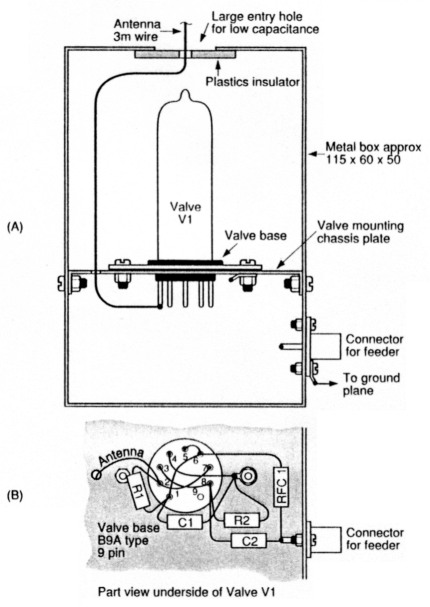
Fig. 4: Diagram showing the advised method of mounting the amplifier in the metal box. For outdoor use, suitable waterproofing precautions must be taken to avoid loss of efficiency and damage to the components.
Testing and warm-up
When you're testing, don't forget that valves take some time to warm up. It's easy to be misled, and most TV producers forget this fact when they're producing wartime plays, and their radio warms up in about two seconds!
As the valve reaches its operating temperature, signal levels will suddenly rise. You should find the bands sounding quite clean, with a little hash from TV sets.
Signals will be much weaker than those received when a full-sized wire dipole is used. Despite this, the signal-to-noise ratio of signals will be better.
Don't be misled by the effects of the automatic gain control (a.g.c.) when assessing results, as it tends to raise noise in-between words. My own impression was that 7MHz sounded more like I4MHz. and listening was much more pleasurable.
Intermodulation
Active antennas are often accused of causing intetmodulation when there are strong signals. However, this valve circuit is difficult to overload itself, and does not have enough gain to overload the receiver. Normally, it's the receiver mixer which is the vulnerable item, and it is important not to use too much gain ahead of this stage.
It's worth mentioning that arrays of active antennas can be built. For instance, a 2-element array could be made by using two active antennas spaced a quarter of a wavelength apart. Such an array has virtually no coupling between the antennas to complicate matters.
Closer spacings, other than quarter wavelengths can also be used. But, if you do try closer spacings, there will be a reduction in signal which may not be tolerable.
Fun Project
I've presented this valved active antenna as a fun project. It's very easy and interesting. If you want to try a solid state version, then by all means go ahead, but I suggest you use a f.e.t.
If you're thinking of purchasing an active antenna, be most careful over the specifications. This is because normally simple statements like 'gain' and 'noise factor', need careful definition when the amplifier is intended for this unusual application where the source is a very high impedance.
Have fun with your valved active antenna. It's virtually 'bomb-proof' and great fun to build and use.
Part list
| Resistors: metal film 0.6W type. | ||
|---|---|---|
| 1kΩ | 1 | R2 |
| 15kΩ | 1 | R1 |
| Capacitors: high voltage disc ceramic | ||
| 1 nF | 2 | C2, 3 |
| 10nF | 1 | C1 |
| Inductors | ||
| Radio frequency choke | 2 | RFC1, 2 100µH (max resistance 1.5Ω) |
| Valve | ||
| ECC81/12AT7 | 1 | V1 (see text) |
| Miscellaneous | ||
| Valveholder (B9A), suitable aluminium box (die-cast with rubber seals for outdoor use), coaxial cable plugs and sockets, self-amalgamating tape (foi sealing purposes). The inductors, LI and L2, can be made up by winding 40 turns of thin connecting wire over a suitable length of ferrite rod. Virtually any resistors will do for the circuit, and Maplin 0.6W metal film types are suitable. High voltage disc ceramic capacitors (Maplin JLO3D and 1LO4E are suitable). | ||