VLF Up-Converter
Down below the long wave band there are many interesting signals to he heard, both natural and manmade. Adrian Knott G0KSN shows you how to make these signals audible on a Conumt meat ions receiver.
Some readers will doubtless possess a communications receiver. Whilst the majority of these sets perform very well in the h.f. band, most do not cover the frequency range below 500 kHz. My interest in l.f./v.l.f. was aroused some years ago, when I found an article on decoding time transmissions from the atomic clock signal on MSF (on 60 kHz).
Transmissions below 150kHz, potentially, have ranges of many thousands of kilometres. Signals in this band include radio navigation, standard frequencies and submarine communications. There are also naturally occurring phenomena between about 1 kHz and 20-30 kHz.
The converter described here translates frequencies, in the range 500 Hz to 150 kHz, up into the 3.5 MHz amateur band. A standard communications receiver will then allow you to listen in on this rather strange, and intriguing part of the electro-magnetic spectrum. If you look at Fig. 1 you will see the range of signals.
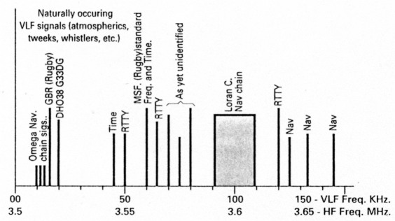
Fig. 1: Many, interesting signals are to be found below the long wave broadcast band. Using the up-converter described here, will make them audible in the 3.5 MHz band as shown here.
Converting A Signal
Converting a 60kHz signal to 3.560 MHz presents no real problem, but consider converting 10 kHz up to 3.510 MHz. With the converter local oscillator running at 3.5 MHz and a conventional mixer all hell is let loose.
What we have done is to generate a very strong signal (the l.o.) only 10 kHz away from our wanted (and very much weaker) signal. The result of the strong nearby signal, is to overload the front end of the communications receiver (and probably the i.f stages as well if a mediocre filter is used). This will result in our v.l.f. signal being lost under an enormous blocking signal.
The answer to the converter problem is to use a balanced mixer in the up-converter. Using a balanced mixer, results in a great reduction in the l.o. breakthrough. Even the most elementary of receivers should resolve the signal.
Final Design
The circuit in Fig. 2 is the final design I arrived at. Since we are dealing with low frequencies, the r.f. amplifiers may be broad band and rolled off gently above 150 kHz.
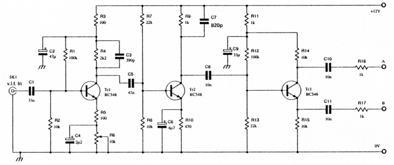
Fig. 2a: The circuit of the pre-amplifier and phase splitter section of the project.
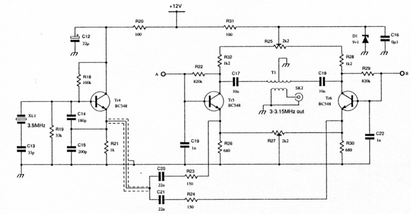
Fig. 2b: The local oscillator and balanced mixer section. Points A and B couple to the similarly marked points in Fig. 2a.
The v.l.f. signal from the loop is fed into the base of Tr1 via C1. This, in conjunction with the input impedance of the first stage, forms a high pass filter from about 500Hz upwards.
Stage gain is adjustable with R6, while capacitor C2 in the collector circuit of Tr1 reduces gain above 150 kHz. Transistor Tr2 is another gain stage (C7 reduces gain above 150kHz), feeding the phase splitter Tr3. This phase splitter stage, Tr3, provides two signals of the same level but 180° out-of-phase with each other at outputs A and B.
The transistors, Tr5 and Tr6, form the balanced mixer, and must be matched for gain. The mixer, is symmetrical, but in addition, variable resistors, R25 and R27, improve the balance of the mixer, reducing l.o. breakthrough to a minimum.
Crystal Controlled
The converter oscillator is crystal controlled, and almost any parallel resonance fundamental crystal in the range 3-5 MHz will do. Transistor Tr4 and its associated components form a crystal controlled, Colpitts style, local oscillator.
Capacitor C 13 may be a 60pF trimmer if precise control of frequency is required. The output of the oscillator is taken from the emitter of Tr4, and fed into the mixer via identical networks C20, R23 and C21, R24.
The up-converted output from the mixer, is taken from the collectors of Tr5 and Tr6 via the output transformer T1. Transformer T1 primary is 24 turns, centre-tapped, of 0.27 mm (32s.w.g.) enamelled copper wire. The secondary is 12 turns of the same wire.
In the prototype, T1 was wound on two ferrite beads, or you could use a T50-2 toroidal ferrite core. Both methods are shown in Fig. 3. Either method should prove satisfactory. The number, and ratio, of turns could be experimented with, to give best overall results.
Straightforward
Construction is quite straightforward, and the unit can be built on Veroboard or similar. Layout is not critical, as long as the following guide-lines are observed:
- Keep the input of Tr1l as far away as possible from the output of Tr2.
- Tr5 and Tr6, should be laid out on the board as symmetrically as possible and leads kept as short as possible.
- If the oscillator is some distance from the input to the mixer then it should be fed via screened cable to avoid stray pick up.
- The case of the crystal XL1 should be earthed by means of a short length of wire soldered firmly to the ground.
- The finished projects should be mounted in a metal (preferably die-cast) box in order to minimise local oscillator radiation.
What Antenna
What kind antenna to use? A long-wire antenna has a very high impedance at these frequencies, unless it is several kilometres long. This form of antenna also seems to suffer from electrostatic breakthrough.
A resonant loop system was developed to interface into a load of about 10K. This reduces the Q of the loop for easier tuning, and accommodates the bandwidth of some of the signals found.
The circuit of the antenna is shown in Fig. 4. It consists of 34 turns of 1mm covered copper wire, wound to give a loop diameter of 60cm (yes that's right - 24 of the old inches). A length of thin plywood or hardboard could be used to make up a former for the loop.
The loop is tapped to give 12 possible values of inductance. The tapping points are chosen so that moving along the coil by one tapping point, results in a frequency change of approximately 10%.
A 12-position switch S1 selects the appropriate tap. The parallel resonating capacitors, CL and CH are selected by S2, giving frequency coverage from 11.8 to 36.4 kHz, with CL, and 37.3 to 115.3kHz with CH respectively. Loop resonant frequencies are dependent on the setting of S1 and S2. The two switches, and associated capacitors, may be mounted in the same case as the converter.
The loop itself could be attached to the convener case. Alternatively, the loop could be remotely mounted in an auxiliary case and connected to the converter by means of a short length of coaxial cable. The exact method of construction is a matter of personal preference, and the drawing of Fig. 4 is merely a guide.
Setting Up
To start setting up, apply 12V to the unit, and check that the convener oscillator is working. To do this, tune a receiver to the oscillator frequency.
A short length of wire, connected to the emitter of Tr4, should create quite a strong signal for the receiver. If a known accurate receiver is available, and you have chosen to make C13 variable, then you can set the local oscillator frequency.
Set the b.f.o. on the communications receiver to centre point. Now trim C13 to give zero beat at 3.5 MHz, or whatever other crystal frequency you have chosen. Remove the wire 'antenna' from Tr4, and connect the converter directly to the communications receiver by means of a good quality coaxial lead.
At this point the local oscillator signal may well give a reading of 60dB over S9 on the meter of the receiver. However, by careful adjustment, and re-adjustment, of R25 and R27, it should be possible to reduce the converter oscillator, to become less than an S5 signal.
There is likely to be some interaction between R25 and R27. You may have to carry this step out several times until no further improvement in local oscillator suppression can be achieved.
At the antenna, set S1 to position seven and select CH (10 nF) by means of S2. Then tune the communications receiver to 3.560 MHz (or your chosen crystal frequency + 60 kHz), where you should be able to hear a carrier pulsing at one second intervals.
At my location, this signal is endstopping on the S-meter. Now check that R6 alters the sensitivity of the unit, and that switching in CL, or altering the tapping point, degrades the received signal on 60kHz. If all is well, then no further adjustments are necessary and the unit is ready for use.
Man-made Signals
The unit has been in use at my location for some time now, and some very strange signals have been heard. The omega signals around 12 kHz are reasonably strong and GBR, DHO38, MSF and some other unidentifiable signals are received and indicated full-scale on the S-meter.
Since a lot of the signals present on v.l.f. are either data or RTTY, I think that a computer terminal/modem would be a useful addition to my shack. This is to be my next line of investigation.