Coils, the basic building block
Coils are to be found in almost every radio set, but how can we identify the various types? We asked Stefan Niewiadomski to give us a summary of the Toko 10K and 10EZ series of coils that seem to be found in most sets.
There's a bewildering range of adjustable inductors in the Toko range of coils. However, closer inspection of the specifications of these components reveals great similarities between many of them. The tables used in this article, catalogue the most useful coils in an order that should make these similarities obvious.
The full code for each coil is not shown, only the unique identifying number. In Table 1 take, for example, the full code for coil type 7752, is RW06A7752EK, whereas the full code for the 6438 type is 15FN8A6438EK. Details of these codes can be found in the Bones, Cirkit and Mainline mail order catalogues, along with the ordering code specific to the distributor.
I've only included the coils from Toko's 10K and 10EZ ranges in the tables. These represent the most popular ranges with amateurs, and they crop up most often in articles and kits. There are also ranges of 7mm and 5mm coils which may be encountered occasionally, but these are rather less extensive than the 10K and 10EZ coils and are generally only needed where more miniaturisation is required.
A new aspect to the miniaturisation of coils has recently reached the amateur scene, in the form of surface mount components, but, again, these have not been considered here. Incidentally, the 10, 7 or 5mm dimension refers to the nominal outer width and breadth of the can.
As well as showing the inductance and colour of the core, the tables show the number of tums between the pins for each coil. These figures are useful where a tapping point and/or where the ratio of the primary/secondary winding is needed.
Antenna and oscillator
General purpose, antenna and oscillator coils are shown in Table 1. This range of coils is suitable for use in antenna input filter, oscillators and other general applications.
| Code | Inductance | 1-2 | 2-3 | 1-3 | 4-6 | Colour |
|---|---|---|---|---|---|---|
| 7752 | 630µH | 9 | 114 | 123 | 13 | green |
| 6408 | 360µH | 95 | 3 | 98 | 13 | red |
| 331208 | 330µH | 2 | 92 | 94 | 8 | red |
| 6A356 | 158µH | 3 | 64 | 66 | 7 | blue |
| 80046 | 158µH | 2 | 79 | 81 | 9 | blue |
| 3333 | 45µH | 14 | 41 | 55 | 4 | violet |
| 6438 | 45µH | 10 | 30 | 40 | 8 | violet |
| 3426 | 38µH | 3 | 48 | 51 | 4 | white |
| 6440 | 38µH | 10 | 31 | 41 | 9 | white |
| 32696 | 23µH | 3 | 45 | 48 | 6 | white |
| 3334 | 5.5µH | 7 | 11 | 18 | 3 | yellow |
| 6439 | 5.5µH | 4 | 10 | 14 | 6 | yellow |
| 6441 | 5.5µH | 4 | 11 | 15 | 7 | green |
| 3337 | 5µH | 2 | 23 | 25 | 3 | green |
| 4114 | 4.8µH | 17 | black | |||
| 4173 | 3µH | 15 | 3 | brown | ||
| 4612 | 1.7µH | 11 | 3 | white | ||
| 4613 | 1.7µH | 11 | 1 | white | ||
| 4172 | 1.4µH | 1 | 8 | 9 | 3 | black |
| 2225 | 1.4µH | 1 | 8 | 9 | 1 | black |
| 3335 | 1.2µH | 4 | 4 | 8 | 2 | pink |
| 3767 | 1.3µH | 2 | 6 | 8 | 5 | pink |
| 3428 | 1.1µH | 2 | 8 | 10 | 3 | blue |
| 3766 | 1.1µH | 2 | 6 | 8 | 5 | blue |
In an application where only the primary winding of a coil is used (that is the pin 1-3 winding), there's not much too choose between coils with the same inductance. For example, if a 5µH coil is required, the type 334, 6439, 6440 or 3337 would be suitable. Where these coils differ, is in the primary/secondary ratio and, where the primary winding is tapped. Even so. the 6439 and 6441 are so nearly identical that it is doubtful that any difference in performance could be detected in amateur applications. The 4174 and 4173 are intended for use in 5MHz v.f.o.s and 9MHz (c.i.o.) respectively.
When coil data is tabulated as in Table 1, it can be seen that the colour of the core (or a ring of plastics visible from the top of the can) is a good indication of the inductance of the coil. This can be a good way of identifying a coil which has had its markings rubbed off, which can easily happen when they are handled.
A better way of being sure which coil is which, is to scratch the codes onto the cans when coils are received. Then, even if the original markings are lost, the scratched code will still be visible. (The method I use is to paint fishing rod varnish, available from fishing tackle suppliers, over the original markings. Editor)
Lower frequency
The coils shown in Table 2. are suitable for use in lower frequency i.f. strips in the range 455-468kHz. In practice there's not much to choose between coils which are specified for use at 455kHz and 468kHz.
| Code | Capacitor | 1-2 | 2-3 | 1-3 | 4-6 | Colour |
|---|---|---|---|---|---|---|
| 11098 | 180pF | 140 | 25 | 165 | 4 | orange |
| 12374 | 180pF | 127 | 38 | 165 | 6 | yellow |
| 11100 | 180pF | 104 | 36 | 140 | 20 | black |
| 1A589 | 180pF | 15 | 125 | 140 | 6 | blue |
| 1A590 | 180pF | 80 | 60 | 140 | 15 | white |
| 4A888 | 430pF | 55 | 55 | 110 | 15 | black |
| 17104 | 180pF | 98 | 67 | 165 | yellow | |
| 17105 | 200pF | 68 | 68 | 136 | 68 | yellow |
| 41996 | 180pF | 43 | 164 | 16 | red | |
| 41997 | 180pF | 19 | 164 | 16 | blue |
Enough adjustment range is available for either type of coil to be used at either frequency. In fact, there is sufficient adjustment to go considerably above 468kHz and below 455kHz if required.
The different ratios of primary/secondary windings are intended to give different input/output impedance transformations. The 4A888 and 17105 are particularly useful, since they have centre-tapped primaries, making them useful for integrated circuit i.f amplifiers which have push-pull outputs, such as the MC1350 or the NE/SA602.
Generally suitable
All the coils shown in Table 3. were designed for use in f.m. i.f. systems at 10.7MHz. However, coils designed for 10.7MHz are generally suitable for use at 9MHz, a popular i.f. with amateurs. The adjustment available by screwing the core in and out is usually about ±30% of the nominal value.
| Code | Capacitor | 1-2 | 2-3 | 1-3 | 4-6 | Colour |
|---|---|---|---|---|---|---|
| 30466 | none | 6 | 3 | 9 | 1 | pink |
| 30465 | 120pF | 6 | 3 | 9 | 1 | brown |
| 4520 | 50pF | 8 | 7 | 15 | 1 | red |
| 3892 | 82pF | 7 | 7 | 14 | 2 | red |
| 3893 | 82pF | 7 | 7 | 14 | 3 | red |
| 3894 | 82pF | 7 | 7 | 14 | 4 | red |
| 1506 | 51pF | 3 | 12 | 15 | 2 | black |
| 6184 | 82pF | 10 | 3 | 13 | 3 | black |
All the coils except the 30455 have an internal capacitor fitted which resonates the coil at the i.f. frequency, which can be set exactly by adjusting the coil's core.
Again, the different ratios of primary/secondary windings available (for example, with the 3892, 3893 and 3894) are intended to give different input/output impedance transformations. As in the low i.f. coil range, there are coils in this category, namely the 3892, 3893 and 3894, that have centre-tapped primaries.
Standard Pins
Luckily, there's a standard layout used for pins, at least on the Toko range of coils. The pin numbers for the windings shown in the tables refer to the pin-out shown in Fig. 1. Here the coil is viewed as looking onto the pins, or from the track side of the p.c.b.
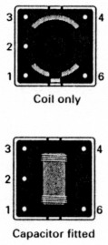
Fig. 1: Two common pin-outs, as seen from below. The lower coil has a capacitor fitted to become an r.f. transformer. See Fig. 2.
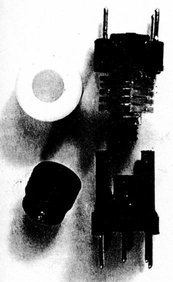
Fig. 2: These are the two most commonly seen formats. The lower one may have a capacitor fitted as shown Fig. 1.