Reducing IMD in high-level mixers
If the question is "How can I get the greatest dynamic range out of diode mixers?" a high-level mixer is often the answer. Come learn how to get great performance out of these useful devices.
About four months before thiswriting, I started designing a new HF transceiver. I live in Los Angeles, here there are many other active hams and several within a one-mile radius. I wanted a good strong receiver that would be immune to interference from strong local signals on the same band where I was listening signals. After looking at several QST and QEX articles, I decided that a passive high-level mixer was the best solution.
All went a well until I finished construction and tested the receiver. The measured intermodulation distortion (IMD) was no anywhere near the performance expected. The actual third-order intercept (IP3) was 15 dB lower than could be achieved according to the manufacturer's published data.
My design followed the guidelines published in amateur Radio publications, but there must have been something that I didn't know. Thus, I started performing a series of tests with different terminations on the mixer's LO, RF and IF ports to see what would solve the problem. What I found can help you use those types of mixers more effectively.
| ZFY-1 Specifications | |
|---|---|
| LO/RF IF LO Power RF 1-dB Compression Point Conversion Loss, 0.2-250 MHz Conversion Loss, 0. 1 -500 MHz LO-RF Isolation, 0.1-1 MHz LO-RF Isolation, 1-250 MHz LO-RF Isolation, 250-500 MHz LO-IF Isolation, 0.1-1 MHz LO-IF Isolation, 1-250 MHz LO-IF Isolation, 250-500 MHz |
100 kHz - 500 MHz 10 kHz - 500 MHz 23 dBm 20 dBm 4.9 dB typ, 6.0 dB max 7.5 dB max 20 dB min, 40 dB typ 35 dB min, 46 dB typ 30 dB min, 40 dB typ 23 dB min, 37 dB typ 35 dB min, 46 dB typ 30 dB min, 40 dB typ |
The Mixer
The Mini-Circuits ZFY-1 doubly balanced mixer (DBM)(1) used in the transceiver has impressive specifications and is usable from the 160-meter to 70-centimeter amateur bands (see Table 1). Other models are available for applications through 3 GHz. Mini-Circuits application notes indicate that the third-order intercept of a DBM is approximately 15 dB higher than the 1-dB compression point. This mixer should be capable of a third-order intercept of +35 dBm (3 W!) if used properly.
Manufacturers test DBMs with broadband 50 Ω terminations at all ports so these numbers do not show exactly what will happen when the mixer is embedded in a transceiver. However, they are reproducible and do give a good indication of relative performance. With the proper design, performance close to these numbers should be possible.
Testing the Conventional Wisdom
I initially assumed that termination of the mixer's IF port was the only important requirement for using a DBM. Competent advice told me that the IF port must be terminated in a 50 Ω broadband load, but other ports were not very sensitive to their terminations. The following passage from Solid State Design for the Radio Amateur(2) is similar to those in many other articles in amateur literature:
"After initial measurements were performed with broadband terminations at allports, tuned circuits were inserted in various lines to the mixer. These were single-tuned LC circuits. The results were profound! When a single-tuned circuit was put in the IF port it had the effect of still presenting a 50 Ω termination at the desired IF of 9 MHz. (The RF energy was at 14 MHz and the LO was at 23 MHz.) However, at frequencies other than the 9-MHz IF, the impedance was highly reactive. This has the effect of decreasing the output intercept from +15 dBm to +5 dBm in several of the mixers studied. The conversion loss did not change significantly."
"When a narrow-band termination was used at the RF and LO ports of the mixer, a degradation in output intercept was also observed. However, it was not nearly as severe as that seen at the IF port."
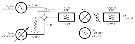
Fig 1 - IMD Test Setup
This testing was done on a low-level mixer with a + 10-dBm LO. I was using a high-level mixer with a +23-dBm LO. The LO and IF frequencies were identical. Perhaps there was a difference in behavior of high-level mixers. The circuit used to test this assumption is shown in Fig 1. A crystalcontrolled oscillator and an HP-8640 signal generator were used to generate RF signals at 14.318 MHz and 14.218 MHz, respectively, which were combined in a hybrid combiner and sent to the mixer under test. The output level was 4 dBm per tone. This is a typical setup for two-tone IMD testing. For more information on IMD, see The ARRL Handbook.(3) The LO frequency range used was 23 to 23.4 MHz and the IF was 9 MHz. The LO was tuned to place each distortion product into the IF filter passband for measurement.
The two tones pass through a threepole RF band-pass filter connected to the RF port of the mixer. The band-pass filter has a loss of 3 dB. The mixer's LO port was driven directly by an amplifier with an untuned output. The IF port was terminated with an attenuator that fed directly into a KVG XF-91310 2.4-kHz bandwidth crystal filter, matched to 50 Ω by an L network. This was followed by an IF strip and the rest of the receiver. The AGC system is this receiver has a digital readout accurate to ± 1 dB over the range used. The filter exhibits a very low return loss (high SWR) outside its passband. Consequently, return loss outside the passband was determined by the loss in the attenuator as shown in Table 2.
| Attention | Return loss | SWR |
| 3 dB | 6 dB | 3:1 |
| 6 dB | 12 dB | 1.67:1 |
| 9 dB | 18 dB | 1.29:1 |
| IF Port Attenuation | IMD | IP3 |
| 0 dB | -33 dBc | +20.5 dBm |
| -3 dB | -37 dBc | +22.5 dBm |
| -6 dB | -40 dBc | +24.0 dBm |
| -9 dB | -41 dBc | +24.5 dBm |
The attenuator was adjusted to determine the mixer sensitivity to IF-port termination impedance and the results are shown in Table 3. This was hardly the improvement expected from the conventional wisdom on DBMs. Only 4 dB of improvement was seen versus the 10 dB expected.
When attenuators were inserted at the RF port in place of the band-pass filter, considerable performance improvement was measured, as shown inTable 4. These results showed that, at least in high-level mixers, the IF port is not the only port sensitive to its termination. An 11-dB improvement could be obtained by paying attention to the RF-port termination.
| RF Port Attenuation |
IMD | IP3 |
| (BPF) | -37 dBc | +22.5 dBm |
| -3 dB | -52 dBc | +30.0 dBm |
| -6 dB | -65 dBc | +33.5 dBm |
| LO Filter | IMD | IP3 |
| no | -37 dBc | +22.5 dBm |
| yes | -49 dBc | +28.5 dBm |
A test with a 3-dB attenuator on the LO port showed no discernable difference in TMD; however, LO waveform symmetry does affect IMD performance, and the LO voltage at the mixer was asymmetrical. I had not seen any quantitative measurements published so I added a filter to the LO port and made the measurements shown in Table 5. The filter was a Π network tuned to 23 MHz with a Q of 3. With this filter in place, waveform symmetry was 50/50 and IMD dropped by 6 dB.
These measurements show that both the IF and RF DBM ports must be well matched and the LO port must be supplied with a clean signal to achieve the best performance. The next problem was how to translate these requirements into a real circuit inside the transceiver.
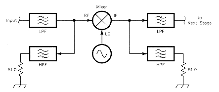
Fig 2 - Parallel high- and low-pass filters for LO termination at RF port.
Achieving Proper Termination at the RF Port
The RF and LO frequencies are the most important and must be terminated properly. When the IF frequency is 1.5 times the highest RF frequency, or higher, proper termination can be provided by parallel low- and high-pass filters with the high-pass or "idler" filter terminated in 50 Ω as shown in Fig 2. Doug Smith, KF6DX, referred to this in a recent QEX article(4) describing a transceiver with a level-17 mixer and a 75-MHz IF. In most cases, a set of band-pass filters that are one-half to one-octave wide precede the low-pass filter to prevent severe second-order intermodulation products. Since LO harmonics fall within the high-pass filter's passband, they are terminated properly. Note that any IMD products from signals inside the band-pass filter's passband that fall outside both the band-pass filter's and the highpass filter's passbands are not terminated.(5) This effect is probably insignificant compared to other sources of IMD.
When the IF is lower than the RF (as with VHF/UHF transceivers or HF transceivers having a first IF in the 3- to 11-MHz range), the mixer RF port requires a band-pass filter to reject the image frequency. This filter is also desirable to reject strong signals that are present from international broadcast stations or nearby amateur transmitters on adjacent bands.
RF band-pass filters can have either very high impedance or very low impedance outside the passband depending on the type of filter. Filters with series capacitors or inductors at their inputs for matching to the first resonator will have high impedances outside the passband, as shown in Fig 3. Filters that have tapped inductors or shunt capacitors on their inputs will have low impedances outside the passband, as shown in Fig 4. Either situation can cause excess IMD in the mixer. Unfortunately, most amateur-built equipment ignores this problem.
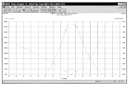
Fig 3 - impedance (M1 1) and attenuation (MS21) plots of a three-pole 1 0-meter band-pass filter with series-capacitor matching at the input port.
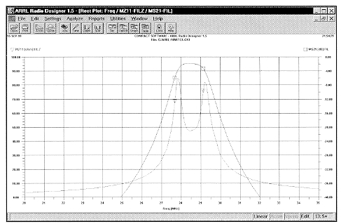
Fig 4 - impedance (MZ1 1) and attenuation (MS21) plots of a three-pole 1 0-meter band-pass filter with tapped-inductor matching at the input port.
To provide a proper termination, a diplexer circuit can be used between the filter and mixer, as is commonly done at the IF port. This achieves a broadband 50 Ω match at one or both ports. However, achieving such a broadband match is only practical for simple filters with a Q of 10 or less. When a multipole filter is needed to achieve steep skirts and reject the RF image frequency, a different approach must be taken. The RF and LO frequencies are the most important and the mixer termination need not be perfect far away from these frequencies. This fact can be used to design a simpler and lower-loss solution for the RF port of the mixer.
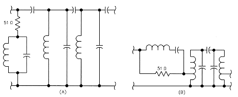
Fig 5-Multipole band-pass filters with out-of-band impedance matching on one port. The filter at (A) has a high impedance outside the passband and the filter at (B) has a low impedance outside the passband.
If the filter presents low impedance outside the passband, place a 50 Ω resistor in series with the filter input. Alternatively, a 50 Ω resistor may be placed in parallel with the filter if it presents a high impedance outside the passband. This gives a good match far from the passband. The resistor can then be bypassed by a series-resonant trap or disconnected by a parallelresonant trap for signals inside the passband, as shown in Fig 5. The trap need not have high Q, as it must only have a bandwidth smaller than the difference between the RF and LO frequencies. It will affect the adjacent resonator slightly, but this may be retuned and no significant distortion of the passband will result.
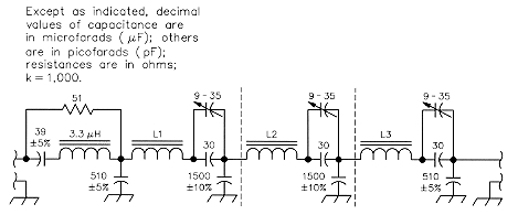
Fig 6 - 20-meter band-pass filter schematic. L1, L2 and U are each 24 turns of #22 AWG enameled wire on a T50-6 powdered-iron torold core (2.5 µH).
A band-pass filter, shown in Fig 6, was designed for the 20-meter amateur band and tested. Figs 7 and 8 show the measured attenuation and return loss. A Chebyshev filter with 0.1-dB ripple and shunt capacitive coupling between resonators was chosen because of its low-pass characteristic. This provides maximum attenuation at the image frequency with a high-side LO. The resonator impedance was chosen to maximize the unloaded Q of the inductor for lowest filter loss.
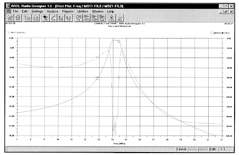
Fig 7 - Predicted attenuation and return loss for the 20-meter band-pass filter.
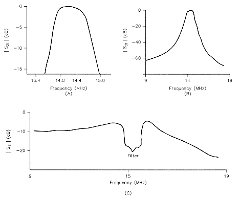
Fig 8 - 20-meter band-pass filter showing measured attenuation (at A and B, S21) and return loss (at C, S1 1).
The filter attenuation is 90 dB at the LO frequency (23 MHz) and over 100 dB at the image frequency (32 MHz). This was achieved with the help of shielding between resonators. The series-resonant trap is constructed with a fixedvalue inductor and capacitor. The inductor is a molded RF choke with a Q of no more than 50. However, the return loss is 23 dB or more at both the LO and RF and insertion loss at 14.2 MHz is only 2.8 dB. The return loss is optimized above the filter passband. This is an advantage when the LO is above the RF. A transformer-coupled design showed better return loss below the filter passband.
Achieving proper termination of the IF port
With low-level mixers, a post-mixer IF amplifier is usually included to provide a broadband termination. When using a high-level mixer in a receiver, the output intercept of the mixer is often equal to or higher than the input intercept of any low-noise amplifier that can be designed to follow it. Any amplifier that is used will also promote IMD in the crystal filter that follows. For example, the ZFY-1 mixer can produce 25 mW of output, which exceeds the 10-mW maximum input rating of most crystal filters without any amplification. It is best to avoid any IF amplifier prior to the first crystal filter. However, crystal filters present a very reactive load outside their very narrow (250 Hz to 15 kHz) passbands.
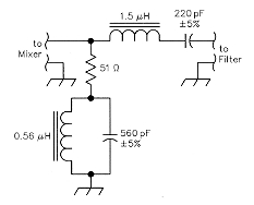
Fig 9 - IF diplexer circuit.
The IF port may be terminated using the same strategy as the RF port. A low Q diplexer will terminate any LO energy at the IF port and eliminate much of the IMD problem. Fig 9 shows such a circuit designed for 9 MHz and Fig 10 shows its characteristics. The low Q (1.6) allows the use of fixed capacitors and inductors and ensures a low insertion loss (0.3 dB) at the IF, while providing a high return loss at the 23-MHz LO frequency. The main crystal filter or a roofing filter can then be connected to the diplexer output. There will be some IMD generated by strong signals inside the diplexer passband and outside the crystal filter passband, but this effect turns out to be minimal compared to othe sources of IMD.
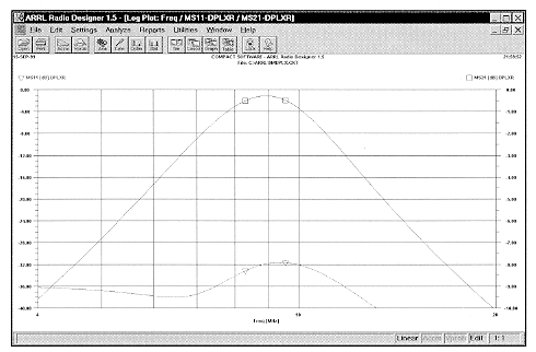
Fig 10 - IF diplexer attenuation and return loss.
Driving the LO Port
It has long been known that it is very important for the LO waveform to be as symmetrical as possible to minimize IMD. In this case, the original LO signal was asymmetrical with a 47/53% duty cycle with respect to zero crossings. Since the LO tunes only a relatively narrow range (the 20-meter amateur band), an network is suitable to filter the input to the LO port. The network shown in Fig 11 has a Q of 2.1 and attenuates the second harmonic of the LO by more than 20 dB. Fixedvalue capacitors and inductors were used for construction; loss is minimal.
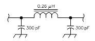
Fig 11 - LO-port filter.
Results
Tests were made using a ZFY-l mixer and two crystal-controlled RF sources with a 25-kHz separation. Crystal-controlled sources were used to ensure that phase noise did not affect measurements at such a close spacing. The twotone RF signal generator circuit is very similar to one previously published in QEX,(6) but uses the oscillator and filter circuit described in my ATR-2000 article.(7) The signal levels at the RF filter were +1 and +2 dBm at approximately 14.300 MHz and 14.325 MHz. The test setup is shown in Fig 12.
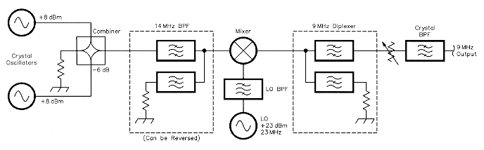
Fig 12 - IMD test setup for data of Table 6.
The LO filter, terminated RF filter, IF diplexer and IF attenuator described above were all constructed using connectors so that they could be removed or reversed to measure their effects. Various circuit configurations were tried and the results are shown in Table 6.
| Test # | LO Filter | RF Filter Terminated | IF Diplexer | IFAttn | IP3 | Δ IP3 |
| 1 | Yes | Yes | Yes | 3 dB | 37.0 dBm | 0 |
| 2 | Yes | Yes | Yes | 0 dB | 33.5 dBm | -3.5 dB |
| 3 | Yes | Yes | No | 3 dB | 30.0 dBm | -7.0 dB |
| 4 | Yes | Yes | No | 0 dB | 24.5 dBm | -11.5 dB |
| 5 | No | Yes | Yes | 3 dB | 30.0 dBm | -7.0 dB |
| 6 | No | Yes | No | 3 dB | 23.5 dBm | -13.5 dB |
| 7 | Yes | No | Yes | 3 dB | 28.0 dBm | -9.0 dB |
| 8 | Yes | No | No | 3 dB | 27.5 dBm | -9.5 dB |
| 9* | Yes | Yes | Yes | 3 dB | 35.3 dBm | 0 |
| 10* | Yes | Yes | Yes | 0 dB | 34.8 dBm | -0.5 dB |
*Test with ZFY-1 option B mixer date code 9448 02; others with date code 9602 03
The results are impressive with all modifications in place (test 1). The third-order intercept point (IP3) is within 1 dB of that achievable according to the manufacturer's application notes. It is very interesting considering that the return loss at the IF port for the down-converted test signals is 6 dB (3:1 SWR). In fact, removing the 3-dB attenuator at the IF port only degraded the IP3 by 3.5 dB. Going beyond 3-6 dB of attenuation had no measurable effect. Clearly, termination of the signals near the IF has a smaller effect on IP3 than any other factor.
When tests were repeated with a second mixer (tests 9 and 10), insertion of the 3-dB attenuator at the IF port made only a 0.5-dB difference. The IP3 with the 3-dB IF attenuator was 1. 7 dB lower and, without the attenuator, was 1.3 dB higher than the first mixer. This is important on the higher HF bands because the IF filter can be connected directly to the IF diplexer to lower the receiver noise figure.(8) An RF amplifier would increase complexity and cause greater degradation in IP3 than was shown with either mixer.
The largest single improvement in IP3 is caused by terminating the LO and image frequencies at the mixer's RF port (test 7). Termination of the LO frequency at the IF port and ensuring symmetry of the LO waveform are also large contributors. Interestingly, the IF diplexer has little effect if the RF port is not terminated properly at the LO frequency (test 8). Proper termination of all ports is required for the best performance.
Notes
- The Mini-Circuits ZFY-1 is the "connectorized" version of the SAY-1 mixer and both use 200 mW of LO injection to achieve high performance levels. The ZFY-1 is $75 from Mini-Circuits distributors but I have also seen it for $30 on the surplus market. A lower-cost mixer with specifications almost as good is the TUF-1 H, which uses a 50-mW LO and is available for $12 new. Surplus Sales of Nebraska, RIF Parts and Down East Microwave are good sources of these or similar high-level mixers at low cost.
- W. Hayward, W7ZOI, and D. DeMaw, W1 FB, Solid State Design for the Radio Amateur (Newington: ARRL, 1977), p 119.
- R. Straw, N6BV, Editor, The ARRL Handbook for Radio Amateurs (Newington: ARRL, 1999), Chapter 15.
- D. Smith, KF6DX, "Signals, Samples, and Stuff: A DSP Tutorial (Part 2)", QEX, May/June 1998, pp 22-37.
- The original signals inside the band-pass filter passband can produce odd-order distortion products outside the band-pass filter passband. For example, if the band-pass filter covers 5 to 7 MHz and the original signals are 5.5 and 6.5 MHz, the mixer will produce third-order distortion products at 4.5 and 7.5 MHz, fifth-order distortion products at 3.5 and 8.5 MHz and so on. The mixer RF port is not terminated in 50 Ω at these frequencies.
- S. Rumley, K160P, "A Precision Two-Tone RF Generator for IMD Measurements", QEX, April 1995, pp 6-12.
- J. Stephensen, KD60ZH, "The ATR-2000: A High Performance Homemade Transceiver, Pt 1" QEX, Mar/Apr 2000, pp 3-15. The crystals shown in Appendix A were pulled up or down in frequency with series connected 12 pF or 10 µH components to achieve a 25.8 kHz spacing between oscillator frequencies. (Part 2 of the ATR series appeared in May/June 2000 and Part 3 in Mar/Apr 2001.)
- Atmospheric noise below 30 MHz is nearly always more than 18 dB above the thermal noise, so a receiver noise figure of 13 dB is adequate for all HF bands.
KD6OZH