Home - Techniek - Electronica - Radiotechniek - Radio amateur bladen - QEX - The Q of single layer air core coils: A mathematical analysis
Exactly what is Q, and how does it affect your circuits? Come along and see.
During the past few years, in the process of writing software for HAMCALC (a collection of programs of interest to Amateur Radio enthusiasts),(1) I kept hoping that I would eventually come across a clear, concise definition of coil Q, complete with a simple equation or two. That did not happen, so 1 decided a more aggressive search through the available literature was in order. I was able to compile definitions and a series of equations (see the Table of Equations) from the following sources (abbreviated titles shown are used throughout this discourse; the full titles are given in the Notes at the end of the article):
The ARRL Handbook(2)
Radiotron Handbook(3)
Terman's Handbook(4)
Electronic Equations Handbook(5)
The main purpose of my investigation was not to introduce any new theory or interpretations, but to see if I could determine a logical sequence and correlation between existing, proven equations. My original published findings dealing with true Q(6) have been expanded and more equations added for inclusion in this paper.
To preserve the integrity of the equations, they are presented in the Table of Equations as they appear in the original reference sources-some in metric units, others in imperial units. This may be a bother when doing calculations manually, for which I apologize, but it presents no problem in the HAMCALC (version 50) computer programs where conversion is automatic.
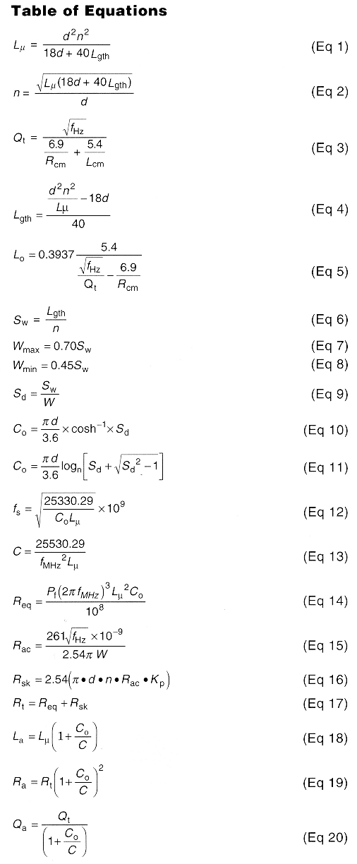
where:
C= added external capacitance required to resonate
Co = distributed capacitance, in pF
d = coil pitch circle diameter, in inches
fHz = operating frequency, in Hertz
fMHZ = operating frequency, in megahertz
fs = self-resonant frequency, in Hertz
Kp = 1.15 (proximity factor)
La = apparent inductance, in microheries
Lcm = coil length, in centimeters
Lgth = coil length, in inches, as a function of inductance
Lo = coil length, in inches, as a function of frequency and
Lµ = true inductance, in microheries
n = number of turns
Pf = 1 (assumed power factor)
π = 3.141593
Qa = apparent Q of coil
Qc = Q of coil due to self -capacitance
Qt = true Q of coil
Ra = resistance due to distributed capacitance, in ohms
Rac = RF resistance in ohms/cm.
Rc = coil pitch circle radius, in centimeters
Req = equivalent series resistance of coil
Ro = equivalent resistance of Cc, in ohms
Rsk = total skin-effect resistance, in ohms
Rt = true resistance, in ohms
Sd = winding pitch/conductor diameter ratio
Sw = winding pitch (center-to-center turn spacing), in inches
W = conductor diameter, in inches
Wmax = maximum conductor diameter, in inches
Wmin = minimum conductor diameter, in inches
Definitions of Q
The 1997ARRL Handbook(7) defines component Q as the ratioX/R, whereX is the reactance of the component and R is the sum of all resistances associated with energy losses in the component. Terman defines two separate values of coil Q:(8) true Qt and observed Q, True Qt (Eq 3) is a mathematical relationship between the radius and length of a "perfect" coil without losses, at a specific frequency when the turn spacing (Eq 6) is within the range of about 0.45 (Eq 8) to 0.70 (Eq 7) times the diameter of the conductor. Observed Q is the value observed by a Q meter.
Radiotron Handbook (page 451) refers to Terman's "observed Q" as "apparent Q". Apparent Qa (Eq 20), is less than true Qt because of the presence of distributed capacity (Eq 10, Eq 11) and resistive losses within the coil that affect the reading of a Q meter.
Terman observes(9) that with a given inductance and coil diameter, Q is maximum when the length/diameter ratio of the coil is in the order of 0.5:1. Actually, some iterative calculation using equation Eq 3 will show the maximum Q increases rapidly with L/d ratio, peaking in the L/d range of about 0.35:1 to 0.45A, then decreases gradually with L/d ratio (see Fig 1). This is consistent with Terman's popular rule of thumb, which probably includes a safety margin.
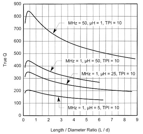
Fig 1 - Maximum Q of typical coils.
Effects of Distributed Capacitance on Q
Terman states:(10) ". The presence of distributed capacity causes a partial resonance that modifies the apparent resistance and reactance of the coil as viewed from the terminals. The apparent series resistances La and Ra ... are related to the true resistance Rt and inductance Lp according to the equations . . ." (The equations(11) that follow Terman's statement are expressed in terms of the ratio [actual frequency] / [self-resonant frequency].
The Radiotron Handbook states:(12) "In all cases the self capacitance of a coil has an apparent effect on its resistance, inductance and Q, and at frequencies considerably below the self resonant frequency of the coil [are] ... Eqs 18, 19 and 20. These equations are expressed in terms of the ratio [self-capacitance of coil] / [external capacitance required to tune Lµ to resonance]. The equations (page 451) produce values identical to the Terman equations, which are not included in the Table of Equations.
Losses
In addition to distributed-capacitance losses, Terman describes four other factors(13) contributing to coil losses as:
- Skin effect(14) (Eqs 15, 16)
- Proximity effect(15) (the proximity factor Kp used in the equations is assumed to be 1.15)
- Dielectric losses
- Eddy-current losses in neighboring objects
Self-Resonance
At some sufficiently high frequency (Eq 12), inductors and capacitors become self-resonant. Just as in a tuned circuit, above that frequency, the capacitor will appear inductive and the inductor will appear capacitive.(16) Because of this, coils are not usually designed for operation above their selfresonant frequency, and any calculated or measured Q above the resonant frequency becomes meaningless in most practical applications.
True Qt versus Apparent Qa
True Qt, which has no losses, increases indefinitely with frequency. Apparent Qa increases with frequency, peaks at a point appreciably less than the self-resonant frequency and then, due to distributed-capacitance effect and resistive losses, decreases until it reaches zero at the coil's self-resonant frequency. These relationships are shown graphically in Fig 2.
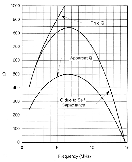
Fig 2 - Values of Q for coil described in Fig 4: 34.7 pH, 27 turns of #14 AWG at 8 turns per inch on a 3-inch diameter form. The coil is 3.375 inches long.
Choosing a True Q Value when designing a Coil
This is mostly ajudgement call based on experience. Because there is little in the literature for guidance, and what little mention there is apparently refers either to apparent Qa or to measurements made by a Q meter under unspecified conditions affecting the interpretation of the meter reading. As a rule, a high apparent Qa is required for narrow bandwidth, minimum bandwidth noise and maximum efficiency.
A useful feature of the HAMCALC Q Calculator program is that as soon as the basic requirements (conductor diameter, inductance and frequency) are entered, it immediately computes and displays the approximate maximum true Q for those factors.
Coil Design
The tricky part in designing a coil with a specific Qt is to arrive at a length and diameter where the length Lgth as a function of inductance (Eq 4) is equal to the length Lo as a function of frequency and true Qt (Eq 5). To design a coil with a specific true Qt, using the equations here, determine five known factors:
- Minimum conductor size required to carry the current
- Required inductance
- Operating frequency
- Desired L/d ratio (lower L/d yields higher Qt)
- Desired true Qt.
Proceed with the design calculations as follows:
- Assume any very small pitch diameter, d, in inches.
- Let Rcm = 2.54d/2. Calculate coil length Lo (Eq 5).
- If Lo is equal or very close to [d x L/d ratio] then proceed to Step 6.
- If Lo < [d x L/d ratio], increase d and return to Step 2.
- If Lo > [d x L/d ratio], decrease d and return to Step 2.
- Calculate Lgth from Eq 4 and confirm that Lo = Lgth
- Calculate number of turns (Eq 2).
- Calculate winding pitch (Eq 6).
- Calculate limits of conductor size (Eqs 7, 8).
- If the specified conductor is within these limits proceed to Step 12.
- Increase L/d ratio and/or decrease Qt, and return to Step 1.
- Calculate conductor circumference P, where P = πd.
- Calculate other factors (Eq 9 through Eq 19).
- Calculate apparent Qa (Eq 20).
Because of the iterative nature of the calculations, this can be a tedious manual operation. To design a coil with a specific apparent Qt using a computer, decide four known factors:
- Minimum conductor size required to carry the current
- Required inductance
- Operating frequency
- Desired true Qt.
With HAMCALC loaded in your computer, start the Coil Q Calculator program, and proceed as follows:
- Select desired measurement units, either metric or inches.
- Select menu item 1 "Coil Specifications for a Specific Q and Frequency".
- Enter the wire diameter.
- Enter the inductance.
- Enter the frequency.
- The computer will display the resultant approximate maximum true Qt.
- The screen will show a display similar to Fig 3. You have the option of changing any or all of the input data at this time.
- Enter your choice of coil diameter within the range displayed. The computer will display complete coil specifications in a manner similar to Fig 4.
- Refer to bar at bottom of screen and press 3 to return to the menu.
- Select menu item 2 to make final minor adjustments to suit a standard wire type and size, a standard coil form diameter and to provide an integral number of turns. These small adjustments may slightly affect the true Qt, which is displayed as each adjustment is made. The entire process takes only a few seconds or perhaps a few minutes if you engage in "what if" speculations in Step 7.
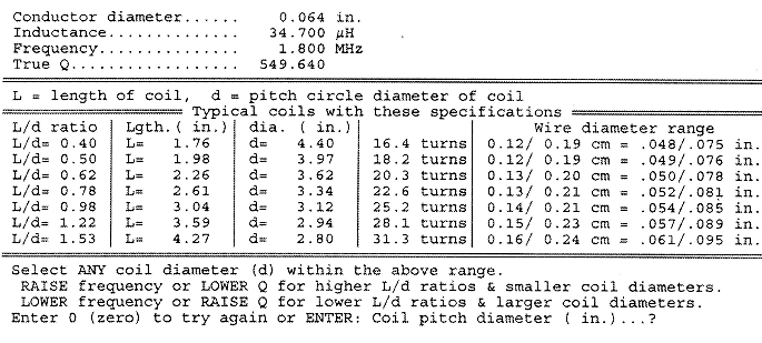
Fig 3 - Inerim results from the coil Q calculator show possible coils for the specified conductor diameter, inductance and frequency.
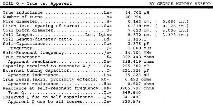
Fig 4 - After selecting a coil diameter of 3.0000", coil Q calculator dislplays the various properties of that coil.
The HAMCALC Coil Equation Calculator may also be found useful in preliminary design and analysis of new or existing single-layer air-core coils. Given only a few of any known properties of a coil, it computes most of the other commonly sought properties, including true Qt and apparent Qa.
Notes
- HAMCALC is free software on CD-ROM containing over 250 programs, obtainable from the author for a modest contribution to cover my costs of materials and airmail shipping anywhere in the world. Ask for Version 50 or later, and send US$7.00 to George Murphy VE3ERP, 77 McKenzie St, Orillia, ON L3V 6V6, Canada.
- P. Danzer, N1II, editor, The 1997 ARRL Handbook for Radio Amateurs (Newington, Connecticut: ARRL, 1996).
- F. Langford-Smith, editor, Radiotron Designer's Handbook, 4th edition, 1952, Wireless Press (Australia), reproduced and distributed in the US by the Tube Division, Radio Corporation of America, 1936.
- F. E. Terman, Radio Engineer's Handbook, (New York: McGraw-Hill, 1943).
- S. J. Erst, Electronic Equations Handbook, (Blue Ridge Summit, Pennsylvania: TAB Books, 1989).
- G. Murphy, "The Elusive Q of Single-Layer Air-Core Coils", CQ Magazine, May 1999, pp 24-31. In that article under the heading "Q quations", the "n =..." equation should read "Qt =..." as it does in Eq 3 of this article.
- The 1997 ARRL Handbook, p 6.21, equation 43.
- Terman, p 916 equation 15.
- Terman, p 74 paragraph 18, "Q of Single Layer Coils".
- Terman, p 85.
- Terman, p 85 equations 102 and 103.
- Radiotron Handbook, p 451, Section 2(i).
- Terman p 74 paragraph 18, "Factors Contributing to Coil Losses".
- Terman, p 35 equation 6.
- Terman, p 36 Fig 6. According to this graph, for current in the same direction in two wires spaced two diameters apart the proximity factor, C, is about 1.15.
- The 1997ARRL Handbook, p 10.12, "Self-Resonance".
- You can download this package from the ARRL Web at www.arrl.org/qexfiles/. Look for Murphy0901.ZIP.
Equation Sources
Eq 1: 1997 ARRL Handbook, page 6.22 equation 44.
Eq 2: 1997 ARRL Handbook, page 6.22 equation 45.
Eq 3: Radiotron Handbook, page 464 equation F.
Eq 4: Derived from Eq 1 or Eq 2.
Eq 5: Derived from Eq 3 and converted to inches.
Eq 6: Ratio of coil length, in inches, to number of turns.
Eq 7: Eq 8: Radiotron Handbook, page 463 (A), page 464 (B) (G), page 465 (G) (a), page 465 (H) (d).
Eq 9: Ratio of coil winding pitch to conductor diameter.
Eq 10: Electronic Equations Handbook, page 6 equation 1-38.
Eq 11: Eq 10 with cosh function re-phrased to suit calculation by computer.
Eq 12-13: Derived from the ARRL Handbook, page 6.35 equations 89 to 92.
Eq 14: Terman Handbook, page 34 equation 5.
Eq 15: Terman Handbook, page 35 equation 6.
Eq 16: Total conductor-resistance equation Rac x conductor length, in cm.
Eq 17: Total resistance.
Eq 18-20: Radiotron Handbook, page 451 (1).
About Q Meters
The interpretation of readings displayed by Q meters is beyond the scope of this article. According to the manual I have for one of these instruments, there is a lot more to measuring coil Q than merely attaching a couple of test leads, pushing a button and getting an instant result. If anyone wants an article about how to read a Q meter, it won't be written by me. I don't even understand the manual!
VE3ERP.