Understanding Switching Power Supplies, Part 2
Come learn design techniquesfor the real world.
In the first part of this article,(1) we looked at basic circuit configtions and operation. In this installment, we will look at designing powersupplies with real-world transformers and coils. We will look in detail at the datasheet for ferrite material 77 for transformers and at various powdered-iron materials for smoothing chokes. We will look at material 77 from Fair-Rite Corporation because Amidon Inc carries transformer cores in this mix, and they have long supplied the Amateur Radio community with reasonable ordering requirements. Amidon also carries other mixes, but mix 77 was most available when I checked their inventory. We will also look at the relative merits of materials from other suppliers.
The examples in this installment will have requirements that appear as if by magic. The information on how to decide turns ratios, inductance values, ripple current, etc will come in a later installment.
Properties of Real Magnetics
Our discussion of basic circuits assumed ideal inductors and transformers. Real inductors have the properties of inductance, resistance and capacitance plus losses due to the core material. The inductor section of the ARRL Handbook gives a good description of the losses in magnetic cores. The primary properties we must consider when choosing a core are permeability, magnetic losses (hysteresis), maximum flux density (saturation) and core temperature.
Ferrite is a ceramic composed of magnetic metal oxides mixed with ironoxide. The most popular magnetic materials are manganese and zinc or nickel and zinc. The magnetic materials are mixed with an organic binder and fired in a kiln to make a ceramic in the same manner that ceramic dishes are made. Since they are ceramics, ferrites can be produced in many shapes simply by varying the mold shape. They can also be machined after firing to produce smooth surfaces and precise dimensions. Ferrite cores for power use are typically made of manganese-zinc compounds for higher permeability. Eddy-current loss in ferrite is quite low in the normal operating range of the material because of the insulating property of the oxides and the binder. The resistance of the material is quite high compared to metals. Eddy-current loss increases as frequency increases.
Powder cores are made by grinding iron or other alloys into fine particles and coating them with an insulating material. Then they are die-pressed and baked. Toroids or rods are common shapes, but some manufacturers can produce other shapes, like E cores. The size of the powder limits the upper frequency limit of powdered cores because of eddy-current losses. The Amidon RF toroids we are familiar with are all powder cores.
Hysteresis (ac flux density) losses are the magnetic equivalent of dielectric losses. Both losses result from the interaction between the electrons of the material and the external field. The electrons absorb part of the field as field intensity increases, but they release part of the energy as heat, rather than returning the energy to the field. As frequency or ac flux density rise, the associated losses in a magnetic Material also rise. Flux density losses can be determined by examining the area inside the B-H curve for the operating conditions. Hysteresis losses limit maximum flux density for frequencies above 20 kHz. Below 20 kHz, the maximum flux density is usually limited by the saturation flux density.
The material of choice for transformer cores in modern switching supplies is a high frequency ferrite. Choke cores can be either powdered iron or ferrite.
Each of the manufacturers has a Web site with large amounts of useful data on their products and in-depth application notes. You will find a list of Web sites at the end of this article. Each manufacturer provides a set of nomographs, figures and procedures for deciding which core to use. Unfortunately, the procedure is different from one manufacturer to another. The procedures presented later are useful with the bare minimum of information about a set of cores. If you are going to do a rigorous design, it is best to get the full application information from the manufacturer you intend to use, so the design process is streamlined.
Many catalogs and application notes refer to "soft ferrites." This has nothing to do with the mechanical hardness of the material, but instead refers to the magnetic B-H curve of the material. Soft ferrites have a rather low value of residual magnetism when the magnetizing force is removed, whereas hard ferrites have residual magnetism that is nearly identical to the saturation flux density. In addition, soft ferrites have low coerciveforce values. That means it takes very little magnetic force to reduce the residual magnetism to zero. Ceramic permanent magnets are "hard ferrites."
Choosing a Choke Core
Forward converters and buck regulators require a choke inductor to smooth the rectangular pulses to a dc value. The smoothing choke in a highcurrent supply will have a large dc bias current flowing through the windings, which creates a very large magnetic field in the core. An air gap is necessary in the core to ensure that the core does not saturate. If we choose to use a ferrite core, it must have a gap when the core pieces are assembled. This gap allows flux leakage and can be a problem for interference and control of the effective permeability as the gap gets large. A powder core has an inherent distributed gap caused by the insulating material around the magnetic particles. Most designers prefer to use powdered core toroids for smoothing chokes because of cost, control of permeability and ease of assembly. The limiting factors for choke cores are saturation and temperature rise.

Fig 1-Change in initial permeability versus ac flux density in powdered-iron cores.
The permeability of magnetic materials is not constant. It varies as a function of ac flux density, frequency, dc bias current and temperature. Fig 1 gives a graph of the change in initial permeability for various levels of ac flux in various Micrometals powdered core materials. The dc bias current that is present in continuous mode operation decreases the permeability of the material as shown in Fig 2.

Fig 2-Decrease of permeability due to dc bias in powdered-iron cores.

Fig 3-Decrease of permeability due to frequency in powdered-iron cores.
Fig 3 shows the change in permeability versus frequency. Micrometals powder cores show a minor, linear change of permeability with temperature. Mix-26 has a temperature coefficient of 825 ppm/°C and -52 has 525 ppm/°C. Fig 4 shows the B-H curves for four Micrometals materials including -26 and -52.

Fig 4 - B-H characteristics of powdered-iron cores.
Mix -26 (yellow with white) and -52 (green with blue) are the least expensive of the powdered core materials. They also exhibit the largest change in permeability due to environmental factors. Mix -52 is recommended for frequencies above 100 kHz and mix -26 for frequencies below 100 kHz. These two materials are the most likely ones to find in computer power supplies when scrounging for parts. If your design requires a large output current range (such as a SSB transmitter supply) and constant inductance is required, then mixes -18 and -8 are the preferred materials. These have much more stable characteristics with changes in flux and frequency. The trade-off is that permeability is lower (55 and 35) and cost is approximately doubled for identically sized cores. A larger core is also required, so the final cost of the core can increase by four times or more. Unfortunately, neither Amidon nor Micrometals has all of their application information on the Web. Micrometals will provide their application catalog on request. It is very useful if you need to pick the optimum core. I have included the bare minimum of data from Micrometals to allow you to follow the examples.
As long as the ripple current is approximately 1% of the total de current, the only temperature rise will be due to copper losses. The temperature rise will be greater when ripple current rises because of hysteresis losses in the core. You must also consider the increase in inductance that will occur as permeability increases when ripple current increases to 10% or 25% of total current.
| Wire area | Current capacity, A (listed by columns of A/cm2) | |||||||
|---|---|---|---|---|---|---|---|---|
| Wire size (AWG) | Resitance Ω/m | Wire OD (cm) (heavy build) | Circular mils | cm2 (x0.001) | 200 | 400 | 600 | 800 |
| 8 | 0.00207 | 0.334 | 18000 | 91.2 | 16.5 | 33.0 | 49.5 | 66.0 |
| 9 | 0.00259 | 0.298 | 14350 | 72.7 | 13.1 | 26.2 | 39.3 | 52.4 |
| 10 | 0.00328 | 0.267 | 11500 | 58.2 | 10.4 | 20.8 | 31.2 | 41.6 |
| 11 | 0.00413 | 0.238 | 9160 | 46.4 | 8.23 | 16.4 | 24.6 | 32.8 |
| 12 | 0.00522 | 0.213 | 7310 | 37.0 | 6.53 | 13.1 | 19.6 | 26.1 |
| 13 | 0.00656 | 0.1902 | 5850 | 29.6 | 5.18 | 10.4 | 15.5 | 20.8 |
| 14 | 0.00827 | 0.1714 | 4680 | 23.7 | 4.11 | 8.22 | 12.3 | 16.4 |
| 15 | 0.01043 | 0.1529 | 3760 | 19.1 | 3.26 | 6.52 | 9.78 | 13.0 |
| 16 | 0.01319 | 0.1369 | 3000 | 15.2 | 2.58 | 5.16 | 7.74 | 10.3 |
| 17 | 0.01657 | 0.1224 | 2420 | 12.2 | 2.05 | 4.10 | 6.15 | 8.20 |
| 18 | 0.0210 | 0.1095 | 1940 | 9.83 | 1.62 | 3.25 | 4.88 | 6.50 |
| 19 | 0.0264 | 0.0980 | 1560 | 7.91 | 1.29 | 2.58 | 3.87 | 5.16 |
| 20 | 0.0332 | 0.0879 | 1250 | 6.34 | 1.02 | 2.05 | 3.08 | 4.10 |
| 21 | 0.0420 | 0.0785 | 1000 | 5.07 | 0.812 | 1.63 | 2.44 | 3.25 |
| 22 | 0.0531 | 0.0701 | 810 | 4.11 | 0.640 | 1.28 | 1.92 | 2.56 |
| 23 | 0.0666 | 0.0632 | 650 | 3.29 | 0.511 | 1.02 | 1.53 | 2.04 |
| 24 | 0.0843 | 0.0566 | 525 | 2.66 | 0.404 | 0.808 | 1.21 | 1.62 |
| 25 | 0.1063 | 0.0505 | 425 | 2.15 | 0.320 | 0.641 | 0.962 | 1.28 |
| 26 | 0.1345 | 0.0452 | 340 | 1.72 | 0.253 | 0.506 | 0.759 | 1.01 |
| 27 | 0.1686 | 0.0409 | 270 | 1.37 | 0.202 | 0.403 | 0.604 | 0.806 |
Table 1 is a wire table that describes the characteristics of various wire gauges. The columns of interest are the resistance/meter and the current at various current densities. A current density of 600 A/cm2 corresponds to roughly 40°C rise and 400 A/cm2 corresponds to roughly 20°C rise.
| Red E cores 500 kHz to 30 MHz (µ=10) | |||
|---|---|---|---|
| No. | OD (in) | ID (in) | H (in) |
| T-200-2 | 2.00 | 1.25 | 0.55 |
| T-94-2 | 0.94 | 0.56 | 0.31 |
| T-80-2 | 0.80 | 0.50 | 0.25 |
| T-68-2 | 0.68 | 0.37 | 0.19 |
| T-50-2 | 0.50 | 0.30 | 0.19 |
| T-37-2 | 0.37 | 0.21 | 0.12 |
| T-25-2 | 0.25 | 0.12 | 0.09 |
| T-12-2 | 0.125 | 0.06 | 0.05 |
| Black W cores 30 MHz to 200 MHz (µ=6) | |||
| No. | OD (in) | ID (in) | H (in) |
| T-50-10 | 0.50 | 0.30 | 0.19 |
| T-37-10 | 0.37 | 0.21 | 0.12 |
| T-25-10 | 0.25 | 0.12 | 0.09 |
| T-12-10 | 0.125 | 0.06 | 0.05 |
| Yellow SF cores 10 MHz to 90 MHz (µ=8) | |||
| No. | OD (in) | ID (in) | H (in) |
| T-94-6 | 0.94 | 0.56 | 0.31 |
| T-80-6 | 0.80 | 0.50 | 0.25 |
| T-68-6 | 0.68 | 0.37 | 0.19 |
| T-50-6 | 0.50 | 0.30 | 0.19 |
| T-26-6 | 0.25 | 0.12 | 0.09 |
| T-12-6 | 0.125 | 0.06 | 0.05 |
| Wire size | T-200 | T-130 | T-106 | T-94 | T-80 | T-68 | T-50 | T-37 | T-25 | T-12 |
|---|---|---|---|---|---|---|---|---|---|---|
| 10 | 33 | 20 | 12 | 12 | 10 | 6 | 4 | 1 | ||
| 12 | 43 | 25 | 16 | 16 | 14 | 9 | 6 | 3 | ||
| 14 | 54 | 32 | 21 | 21 | 18 | 13 | 8 | 5 | 1 | |
| 16 | 69 | 41 | 28 | 28 | 24 | 17 | 13 | 7 | 2 | |
| 18 | 88 | 53 | 37 | 37 | 32 | 23 | 18 | 10 | 4 | 1 |
| 20 | 111 | 67 | 47 | 47 | 41 | 29 | 23 | 14 | 6 | 1 |
| 22 | 140 | 86 | 60 | 60 | 53 | 38 | 30 | 19 | 9 | 2 |
| 24 | 177 | 109 | 77 | 77 | 67 | 49 | 39 | 25 | 13 | 4 |
| 26 | 223 | 137 | 97 | 97 | 85 | 63 | 50 | 33 | 17 | 7 |
| 28 | 281 | 173 | 123 | 123 | 108 | 80 | 64 | 42 | 23 | 9 |
| 30 | 355 | 217 | 154 | 154 | 136 | 101 | 81 | 54 | 29 | 13 |
| 32 | 439 | 272 | 194 | 194 | 171 | 127 | 103 | 68 | 38 | 17 |
| 34 | 557 | 346 | 247 | 247 | 218 | 162 | 132 | 88 | 49 | 23 |
| 36 | 683 | 424 | 304 | 304 | 268 | 199 | 162 | 108 | 62 | 30 |
| 38 | 875 | 544 | 389 | 389 | 344 | 256 | 209 | 140 | 80 | 39 |
| 40 | 1103 | 687 | 492 | 492 | 434 | 324 | 264 | 178 | 102 | 51 |
Table 2 indicates the maximum number of turns that will fit in a single layer on various Amidon toroids. Table 3 lists the magnetic path length for various core sizes.
| Core | T-16 | T-20 | T-25 | T-37 | T-50 | T-68 | T-80 | T-94 | T-106 | T-130 | T-200 |
|---|---|---|---|---|---|---|---|---|---|---|---|
| Path length (cm) | 0.93 | 1.15 | 1.50 | 2.31 | 3.19 | 4.23 | 5.14 | 5.97 | 6.49 | 8.28 | 13.00 |
We also need to account for the change in initial permeability due to dc flux. The formula for percent change in permeability for Micrometals materials has the form:

| Material coefficients | |||||
|---|---|---|---|---|---|
| a | b | c | d | e | |
| 2 | 10000 | -4.99e-3 | -49.5 | 9.16e-6 | 0.0865 |
| 8 | 10090 | 4.26e-3 | 30.9 | 7.68e-5 | -0.0119 |
| 18 | 9990 | 8.36e-4 | 14.4 | 3.92e-4 | 0.0853 |
| 26 | 10090 | 5.05e-3 | 13.1 | 1.17e-3 | 0.0212 |
| 52 | 10240 | 6.71e-3 | 24.7 | 7.75e-4 | -0.0105 |
Table 4 lists the values of these coefficients for the materials of interest.
Let's do an example of a choke design for a forward converter. The design requires an inductance of 15 µH and has a maximum de current of 20 A with 200 mA maximum ripple. We choose to limit the temperature rise to 40°C so we can use the current from the 600 A/cm2 column. We assume we found a T106-26 core in an old PC power supply. All parameters not found in tables here can be found in the Component Data chapter of the ARRL Handbook. A, for this core is 900 µH/100 turns. First, we calculate the number of turns required:
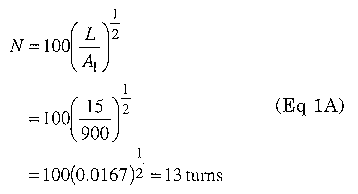
From Table 2 we see that 13 turns of AWG #12 will fit this core. From Table 1 we see that #12 wire will allow 19.6 A. This is close enough to the design goal of 20 A. Now we can verify that the magnetic parameters meet the maximum for the core. Eq 2 gives the magnetizing force applied to a core.

We verify that 50 Oersteds is below the saturation point using Fig 4. We can calculate the change in permeability due to dc bias from Eq 1:
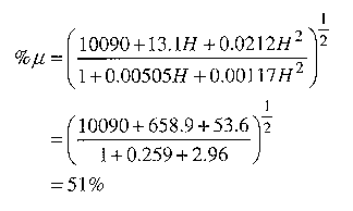
Now we can adjust the number of turns based on the reduced permeability:
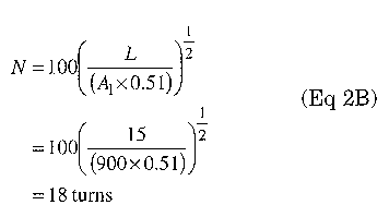
We cannot fit 18 turns of #12 on this core in a single layer, so we have several options. The first is to use the next larger core (T130), so we can fit the proper number of turns of #12. The next option is to put an additional two turns of #12 over the single layer. This will cause a slightly higher temperature rise but we probably have enough margin to do so. The next option is to adjust the inductance value so that we can fit enough wire. In this case we can fit 16 turns of #12, which yields an inductance of 11.8 µH. The last option is to allow greater temperature rise in the inductor and use #14 wire.
Choosing a boost converter core
Ripple current is usually much higher in boost converter designs than in buck converters, so we must account for permeability changes due to ac flux as well as de flux and core losses due to ac flux. The formula for percent permeability change due to ac flux for Micrometals materials has the form:

Table 5 lists the values of these coefficients for the materials of interest.
Material -52 uses the formula:

| Material coefficients | |||||
|---|---|---|---|---|---|
| a | b | c | d | e | |
| 2 | 9970 | 5.77e-4 | 7.29 | -8.96e-8 | -1.18e-3 |
| 8 | 9990 | 4.52e-4 | 11.4 | 8.82e-9 | -8.29e-4 |
| 18 | 10270 | 1.01e-4 | 12.3 | 2.70e-8 | -8.43e-4 |
| 26 | 10600 | 7.21e-5 | 37.8 | -7.74e-9 | -3.56e-3 |
| 52 | 92 | 0.0134 | 2.77 | -3.66e-6 | |
Table 5 also lists these values.
We need to determine the value of B (the ac flux in the core). For a rectangular wave the formula is:

Where E is the peak voltage across the inductor, t is the on time, A is the magnetic cross section of the core, N is the number of turns, L is the inductance, and AI is the peak-to-peak ripple current. (L x ΔI)/N is equivalent to (E x t)/N or volt-seconds/turn.
| Frequency | ||||
|---|---|---|---|---|
| Core | 50 kHz | 100 kHz | 250 kHz | 500 kHz |
| T-37 | 0.86 | 0.54 | 0.29 | 0.18 |
| T-50 | 1.30 | 0.81 | 0.44 | 0.28 |
| T-68 | 1.80 | 1.10 | 0.62 | 0.39 |
| T-80 | 2.20 | 1.40 | 0.75 | 0.47 |
| T-94 | 3.10 | 1.90 | 1.00 | 0.66 |
| T-106 | 4.70 | 3.00 | 1.60 | 1.00 |
| T-130 | 5.00 | 3.20 | 1.70 | 1.10 |
| T-157 | 6.90 | 4.30 | 2.30 | 1.50 |
| T-184 | 10.0 | 6.50 | 3.50 | 2.20 |
| T-400 | 17.0 | 11.00 | 5.90 | 3.70 |
Table 6 gives the volt-microsecond/turn rating of each core size for a 15°C rise due to ac flux core loss for material-26.
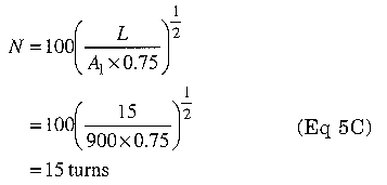
Let's look at an example where the average inductor current is 5.0 A, the peak-to-peak ripple current is 2.5 A and the frequency is 100 kHz. Our design requires an inductor with a minimum inductance of 15 µH and a maximum temperature rise of 40°C. Let's start with the same T106-26 from our previous example. We again calculate 13 turns required for 15 µH based on initial permeability. Now we calculate the reduction in inductance due to de flux:

We verify that 12.6 Oersteds is below the saturation point using Fig 4.
We can calculate the change in permeability due to de bias from Eq 1:
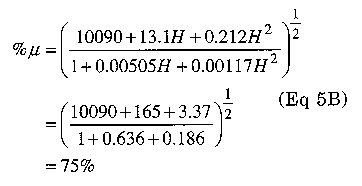
Now we can adjust the number of turns based on the reduced permeability:
Next we calculate the volt-microseconds/turn:
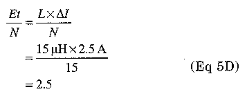
From Table 6 we see that 2.5 volt-microseconds/turn will give us slightly less than 15°C rise in temperature. This allows us at least 25°C rise due to copper loss. We look at Table 1 in the 400 A/cm2 column to find that we need #19 AWG wire. Since #18 and #20 are the most available standard sizes, we can choose #18 to be safe. Since we are slightly under budget on core loss and copper loss, we can probably use #20 if it is convenient.
If the ac flux density is high, the permeability can be affected as well. We can check the ac flux density to see if there is a noticeable effect:

From Fig 2, we see that this level of ac flux will increase the permeability by 30%. This gives us plenty of margin to stay above the minimum inductance.

Fig 5 - Power handling versus frequency for ferrite cores. The curve letters are Magnetics ferrite designations. They don't have direct correspondence to Fair-Rite numbers.
Transformer Properties
Fig 5 shows the power-handling capability of various ferrite materials compared to operating frequency. The graph plots a figure of merit (B times frequency) for a constant power loss of 300 mW/cm3. It is important to verify the agreement of graphs between vendors. Magnetics uses 300 mW/cm3 as in Fig 5, whereas Ferroxcube uses 500 mW/cm3.

Fig 6 - Core loss versus temperature for ferrite cores. Curves F, P and R are at 100 kHz with 1000 Gauss; curve K is at 500 kHz with 500 Gauss.
The curve letters are Magnetics ferrite designations. They don't have direct correspondence to Fair-Rite numbers.
Fig 6 gives a comparison of core loss versus temperature for various materials. Notice that the test conditions are not identical for all materials.

Fig 7 - Maximum flux density versus frequency for ferrite cores at 250C and 800C. The curve letters are Magnetics ferrite designations.
They don't have direct correspondence to Fair-Rite numbers.
Fig 7 shows how maximum flux density must be decreased as frequency increases for various Magnetics materials and correlates the flux density to temperature rise. It is possible to use lower-frequency compounds above their optimum frequency (where a curve in Fig 5 starts to turn downward) as long as you account for the greater losses and temperature rise. Temperature is related to surface area; increasing surface area gives more heat dissipation for a given loss. Core loss is related to core volume; a greater volume generates more heat for a given flux density. The problem is that volume increases as the cube of the size and surface area increases as the square of the size. It is interesting that the lowest power loss density occurs at temperatures above 25°C; so elevated temperature operation actually increases efficiency.

Fig 8 - Photo of various ferrite cores.
Fig 8 shows a variety of core shapes and bobbins available for use in induetors and transformers. Cores usually have bobbins available for winding the coils so the final component can be assembled from three or four parts.
Toroid and pot cores provide the largest amount of magnetic shielding. The magnetic field is almost entirely confined to the core. Any amount of magnetic field that is present outside the core represents potential for lessened efficiency. These core types are useful where there is not a lot of heating of the wire due to current flow or heating of the material due to magnetic losses. Generally, these cores are used at power levels below 10 W.
The remaining useful cores are variations of the E shape and the U shape. These cores have very large open areas that allow the heat generated inside the windings to be dissipated to the surrounding air. This space also makes the windings less efficient due to stray magnetic fields outside the core material. A disadvantage of "E" cores is that the primary and secondary are in close proximity, which makes voltage isolation for safety problematic. A standard E core has a square center post. An EC core has a rounded center post, which provides for 11% shorter wire for a winding. It also means that there is less mechanical stress on the windings because the bend radius is larger. U-shaped cores can be used to advantage where high-voltage isolation is required. This shape allows the primary to be wound on a bobbin on one legand the secondary windings to be wound on the opposite leg. U cores are used almost exclusively in television horizontal-output transformers because of the isolation provided.
We must consider the wire for transformer use, because wire can be a source of significant loss. When we looked at choke cores, the wire was a single layer for good thermal characteristics. Transformers are typically wound in layers, with the primary closest to the core and the secondary coils wound on top of the primary. A good rule of thumb (suggested by Magnetics) requires wire sized for 200 to 250 A/cm2 to minimize the heating caused by wire. As wire size gets larger and frequency gets higher, skin effect losses rise and can be as significant as bulk-resistance losses. Commercial transformers may use Litz wire, copper ribbon or copper strip to reduce the effects of frequency. MWS Wire Industries makes a line of square cross section magnet wire. This wire is more expensive and less readily available, but the square shape is advantageous for making compact individual layers that stack well. MWS also manufactures ribbon and strip. They classify ribbon as having a width up to 0.100 inch and strip as having a width of 0.125 to 2 inches. The skin effect is greatly reduced if the conductor is flattened into a thin strip. Many commercial power supplies use strip conductors for the low-voltage, very-high-current windings such as a 20-A, 5-V winding in a PC power supply. These windings are typically only 2 to 5 turns.
Polyester tape is usually wrapped around each layer of the primary winding of an off-line transformer to provide safety isolation between layers of a winding and between windings. Tape that is 1 mil thick is rated for 5500 V of isolation up to 130°C. Tape 2-mils thick is rated for 7000 V. If higher temperature is required, use Kapton polyimide tape, which is rated to 155°C and 7500 V. Copper strip is usually not insulated, so the strip is insulated with polyester tape.
The limiting factor for ferrites at frequencies above 20 kHz is temperature rise due to core losses. Below 20-kHz operation, saturation flux density is the limiting factor. Modern supplies operate at a minimum of 20 kHz and more likely at 100 kHz, or higher. Old articles about choosing a core will refer to the large power capacity of cores with bipolar (ac) drive, as in the half-bridge and the full-bridge converter topologies. This is not true for modern high-frequency designs because the limiting factor is no longer the saturation flux for the core, but rather the heat rise in the core due to hysteresis losses. AC drive circuits offer significantly more margin between the maximum flux and the saturation flux than unipolar drive circuits, but even unipolar drive designs are unlikely to approach saturation flux densities before things start to melt inside the transformer. It is still good design practice to verify the margin for saturation flux under worst-case conditions.
Choosing a forward-converter transformer core
Our example will be a transformer designed for a single switch forward converter operating at 100 kHz with a turns ratio of 5.7:1, input voltage of 310 V and total power of 100 W (12.6 V at 8.0 A). We will choose an Amidon Associates core since they are easy to obtain. From the Amidon web site, we see that the EA-77-500 core is rated for 100 W Since our turns ratio is not an integer, we choose 17 primary turns and 3 secondary turns (5.67:1).
The physical dimensions (in cm) for this core (1/2 core) are:
| W | L | T | Window W | Window L |
|---|---|---|---|---|
| 4.13 | 1.65 | 1.27 | 1.03 | 0.792 |
This gives a volume for two core halves of 13.2 cm3.
Eq 6 gives the flux density:

E = RMS voltage Vp-p/2 for a square wave
A = core magnetic area in cm2 (from data sheet)
N = Number of primary turns
F = Frequency in Hz
For our core:

From Fig 9, we see that this turns ratio will yield 600 mW/cm3. This value will produce a very great temperature rise. We can reduce the flux density by increasing the primary turns. Next we try a 34-turn primary and 6-turn secondary, which yields 712 Gauss. Now we have 150 mW/cm3, which will give approximately 50°C of temperature rise. Total core loss is 13.2 cm3 x 150 mW/cm3 = 1.98 W We have a core temperature of 75°C before we factor wire losses. We need to minimize wire losses if we use this flux density. It appears that we need even more turns in order to lower flux density and reduce temperature rise. A 51-turn primary will reduce the flux density to 475 Gauss and produce a power loss of 40 mW/cm3. This will produce a minimal temperature rise with a core loss of 500 mW. Looking at table 1 for the wire, we see that we need #18 AWG wire for the primary and #10 AWG for the secondary (using 200 A/cm2).
Choosing a flyback-converter "transformer" core
We will design a transformer for a 60-W flyback converter that will provide 5 V at 5 A and ±12.0 V @ 1.5 A. The design requires an inductance of 4.5 mH with an input voltage of 310 V and operates at 20 kHz. We will look again at a material-77 E core from Amidon. We will need a gapped core to ensure that the core does not saturate. We have two options for a gapped core: We can order a gapped core as a special item from Amidon, or we can assemble the core halves using plastic shim stock. Since the input voltage is 310 V, we will need 195 mA average current through the inductor to produce 60 W, but this design has a peak-current requirement that results in ΔI of 2 A. We start with the same EA-77-500 core as in our forward-converter example.
First, we need to find the inductance correction factor caused by the gap from Eq 7:

where
µi = initial permeability from data sheet
G = gap length in mm
1e = effective path length of the core
If we use 0.5-mm shims, the actual gap is 1 min because there is a gap across the center post and in each parallel leg; k is then

Now we can calculate the number of turns required for the inductance:
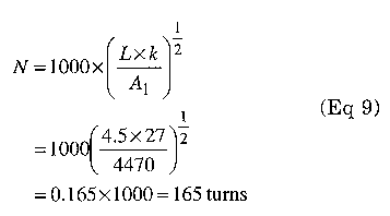
Notice that Amidon and Micro-metals list Al in µH/100 turns for powder cores, and Amidon lists Al in mH/1000 turns for ferrites.
Next, we need to use Eq 5 to determine the peak ac flux density in the core.
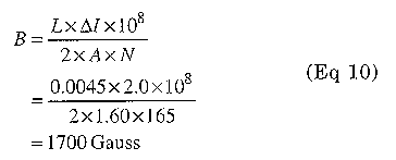

Fig 9 - Power-loss density versus flux density for material 77 at various frequencies.
From Fig 9, we see that the ac flux core loss for this core will be about 100 mW/cm3. Total core loss is 13.2cm3 x 100 mW/cm3 = 1.32 W From Table 1, we can use either #28 or #26 AWG wire for the primary, #12 wire for the 5-V secondary and #18 wire for the 12-V secondary windings.
Sources of Information
I have listed addresses and Web sites for each of the manufacturers mentioned. In particular, Amidon and Magnetics were very helpful in giving information and permission to use their data. Amidon has only limited information on their Web site. You can find additional information on Amidon materials at the ByteMark Web site. ByteMark is a distributor and value added coil-winding service for Amidon and other materials. They also distribute an interesting niche product for "flat transformer" technology.
Amidon Inc, 240 Briggs Ave, Costa Mesa, CA 92626; https://www.amidoncorp.com/.
Fair-Rite, Box J, 1 Commercial Row, Wallkill, NJ 12589; www.fair-rite.com.
ByteMark, 15 10 E Edinger Ave #B, Santa Ana, CA 92705; www.bytemark.com.
Magnetics, Box 391, Butler, PA 16003; www.mag-inc.com.
Ferroxcube USA Inc, 12375 B Pine Springs, El Paso, TX 79928; www.ferroxcube.com.
Errata from Part 1
I made a graphical error in cutting and pasting to make Figs 11 and 12 for the half-bridge and full-bridge circuits. The secondary side in both drawings should have had a full-wave rectifier identical to that in Fig 10. The half-wave rectifier circuit shown will work, but it will be very inefficient. The phase that does not drive the output will only reset the flux in the transformer without supplying current to the load. A full-wave rectifier will deliver the proper amount of current during both phases.
In addition, it was not obvious that the initial condition of the circuit of Fig 4 is with the electronically controlled switch open. The switch does not start closing until the control circuit stabilizes. During the stabilization time, the capacitor and inductor charge up with initial voltage and current.
Notes
WD5IFS.