A high-level accessory front end for the HF amateur bands
Here's an antenna selector / Preselector / attenuator / preamplifier accessory for every HF amateur transcelver. It can improve your receiver's IP2 for out-of-band signals and yield good flexibility.
My father, I4FAF (an old-timer) and I both very much like Amateur Radio as a lifetime endeavor. We do not have backgrounds in electronic engineering, but we do have a lot of practice. My father is a fast builder ofAmateur Radio projects, from printed-circuit artwork drawn by him with CAD software to working units in our home laboratory. Being retired now, he has more time and I help him from time to time.
Our goal is to get more from the Amateur Radio equipment available to us. Our gear is average, not toppriced. I want to improve my skills with DX or weak signals, while I operate in crowded bands during some international contests. Lately, I have discovered the low-frequency bands. They have added more fun.
In 2000, we started to put up (at a flat, country location) a short vertical antenna by Butternut, the HF2V It has the 160-meter coil kit, is top-loaded with four wires (each about 5 meters long) and has six ground radials about 40 meters long for 160, 80 and 40 meters. In winter 2001/2002, we started to test some receive-only antennas, with better signal-to-noise ratios and some directivity, in comparison to the 360° radiation pattern of a vertical antenna.
With the exception of Beverage and a four short vertical system presented by W8JI on his Web site, that still require much space for only -6 to -11dBi; most of the receive-only antennas we have considered are in the low-output category-in the range from -6 to -35 dBi. We have worked with Beverages, EWE, the delta-EWE by K6SE -a variation of pennant-flag antennas and K9AY loops.
We have seen them presented by our trusted teachers in recent artieles in Amateur Radio publications. For example, ON4UN's Low Band DXING (third edition, don't miss reading the new chapter "Special Receiving Antennas"), QST, the Antenna Compendium series and K1ZM's DXing On the Edge-all published by ARRL. There has also been some follow-up on the Internet and on the top-band reflector from W8JI, WA2WVL (EWE antenna), K6SE (delta-EWE and other pennants), WA1ION (pennant with remote variable control of the resistive, in-line termination), K9AY (K9AY loops, now also with remote variable control), K3KY (his Web site has a full collection of contributions, links, about low band antennas), W7IT-TV (rotatable flag) and other well-known authors.1, 2, 3, 4, 5, 6, 7, 8, 9, 10, 11
There is a lot of interest and newcomers frequently ask, "What is the best receiving antenna for the low bands?" I like the Beverage very much, hut my answer must be that I don't know, simply because, until now, I have not been able to test them all. Read K1ZM's book. He agrees that it's better for hams to have more types of antennas available on 160 meters. That is true because of the variable and peculiar propagation conditions on that band. 12, 13, 14
Our beverage and other receive-only antennas
We tested a 177-meter-long, unidirectional Beverage configuration (for USA), up about 2 meters above ground (rural terrain), with a 500 Ω end load (two 1000 Ω resistors parallel connected to a ground rod) and an input impedance ratio of 1:9. The transformer was made of seven quadrifilar turns in parallel using #20 AWG or 0.8-mm-diameter enameled copper wire. The core is an Amidon ferrite FT114-F with a permeability of 3000. Remember that this material, manganese-zinc, has a low bulk resistance, so it is best to cover the core with a thin layer of Teflon tape before winding the wire on it.
See John, ON4UN's, third-edition book for a transformer picture and photo on page 7-17, Fig 7-18: "Modified transmission-line transformer". With our ground characteristics, we had better matching results with this ferrite mix than with the type 43 (permeability of 850) proposed in the book. The thing was tested by us with help of a new MFJ-269 and confirmed by our friend's laboratory-grade spectrum analyzer and tracking generator. ON4UN usually uses high permeability type MN-CX, which was not available to us. A very nice description of how to get a Beverage system to work properly is contained in K1ZM's book, on pages 12-1 to 12-6.
It had been up for only a few days of tests in the winter of 2001/2002 when a 160-meter CW-contest weekend came along. My impressions of performance were very favorable. I had a great time with this antenna. Around 10 US states were worked in one night and with a very clear copy over my short vertical as the transmitting antenna. I still remember those nice signals; of course, most of them were from well-equipped contest stations.
A simple Beverage antenna alone provides about -11 dBi. I don't know exactly the gain of my short vertical but the relative difference in level in decibels does agree quite closely. A phased system of two might have a higher output, at about -6 dBi, as per ON4UN. The other receive antennas' outputs can be, at worst, about -30 to -35 dBi for a delta-EWE loop; see more detailed data in the new chapter in ON4UN's book. We have tried the K6SE delta-EWE, a pennant receive-only antenna that has reasonable dimensions: total wire length is 72 feet, 28 feet on the base side and the high apex is about 17 feet from the base side. It is easy to make it rotatable. In that case, the transformer is differently placed in one lower corner; in the opposite corner is a 950 Ω series resistor and it matches 50 to 950 Ω. K6SE suggested a FT140-43 ferrite with primary and secondary wound at the opposite sides of the core. The primary is 8 turns and the secondary 34 turns with about 990 µH to 1 mH using 20 AWG enameled wire. Remember that the directivity is in the opposite direction from the termination corner, toward the feed point, unlike the Beverage.
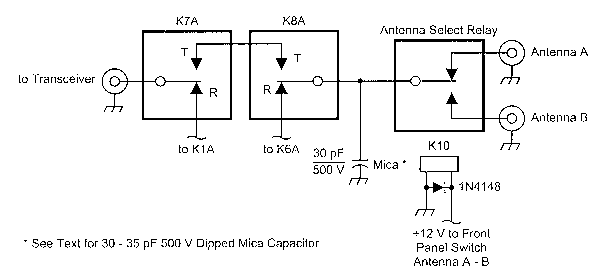
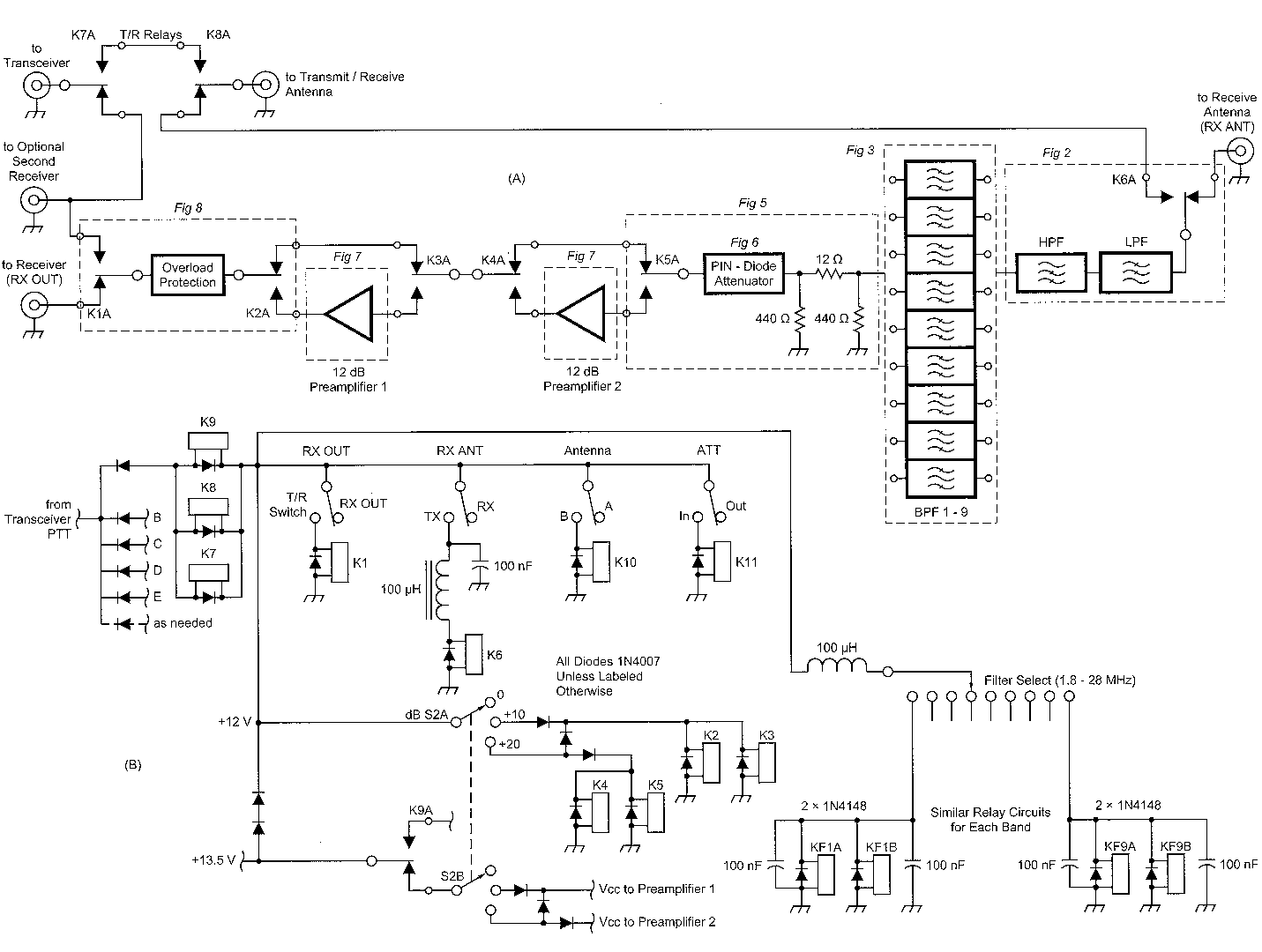
Fig 1 - (left, A) A block diagram of the system. (B) PTT and front-panel controls. The bandpass filters are selected by relays and a front-panel band switch. Preamplifier gain is controlled by a front-panel switch. (C) An additional transmit antenna may be controlled with an added relay and switch.
The Need for an Antenna Processor
We immediately realized the importance of making frequent checks on the receiving antenna and on the transmit/receive antenna to get more flexibility from. the system. That is, to avoid overloading the inside equipment switches when the same functions (antenna 1, antenna 2 and receive-antenna selections) are already built into some recent radios. If needed, you can make maintenance of such switches easy if they are in an outside home-built unit. Now, we don't have the problem of switching among more than two antennas!
In practice, we felt immediately that we needed a complete independent accessory for our transceiver as an outboard tool to deal with the issue of better selectivity in the receive chain. So we stopped our antenna tests and started to think about the design of a complete HF front-end unit with bandpass filtering for our amateur bands only, not for general coverage. Just to simplify and avoid wasting time durmg contest activity with peaking controls, we decided as a practical tradeoff to choose fixed band-pass filters without variable controls. That's why we agree with G3RZP when he wrote in QEX May/June 2002, on page 40: "Are our receivers too sensitive?" The answer is "Probably, but... There are some imponderables. On the LF bands especially, the use of separate receiving antennas producing much lower-level signals hut also lower levels of noise means that requirements may exist at times for the low noisefigure levels that are typically seen in modern receivers".
Obviously, the use of pre-mixer selectivity has a major effect on the performance requirements, although at 7 MHz, the proximity of the broadcast band offers little possibility of really effective filtering in conventional circuits. "... US conditions seem a lot quieter than those in UK". Thus a variable antenna attenuator has obvious advantages, but the attenuation steps need to be much smaller than the 6 or even 20 dB steps provided by commercial transceivers.
I must confirm that it is very hard for us in Europe. We work split on 40 meters to listen to DX and North America among very powerful broadcast AM stations in your portion of the band from 7.150 to 7.300 MHz. The test Peter performed was with a FT-102, which is not a general-coverage receiver but has some ham-band preselectors in it. 1 don't want to use too much attenuation first if the rig used is even poorer.
First, I would like to try a bandpass filter in front of it with a moderate insertion loss, narrower than the internal one. Then, eventually, I will add more attenuation if needed.
A resistive or PIN-diode attenuator is by nature broadband. Insertion loss in a band-pass filter is already an attenuation of RF signals. Outside the filter passband, attenuation inereases on both sides. A practical preselector is desirable in the front end of a receiver to protect all the following stages of the receive chain. In-band insertion loss shouldn't be too high, but 4-6 dB is acceptable since in many cases, you don't need the full sensitivity of your modern receiver. Only when band conditions permit can you switch in one preamplifier to compensate insertion loss.
I do believe that a good receiver must be designed for low IMD in all stages and should haven arrow filter from the beginning of the chain so all the following stages are protected. If not, you need a better following chain. Some system gain-distribution consideration could be done, with one preamplifier switehed in, attenuator off, as shown in Table 1.
| Filters oss (dB) | Atten (dB) | Preamplifier gain (dB) | |
|---|---|---|---|
| Stage gain | -5 | 0 | +12 |
| Total gain | -5 | +7 | |
| Stage gain | 5 | 0 | 3* |
*not measured.27
To calculate cumulative NF and cumulative input intercept, please look at Chapter 4, "Receiver Design", in W E. Sabin and E. 0. Schoenike, Single Sideband Systems & Circuits, 2nd Ed., MeGraw Hill, now also "HF Radio System & Circuits".15
ARRL laboratory test 16 have reported about the good performance of the Elecraft K2 receiver with respect to 5 kHz spacing, two-tone IMD test in comparison with some higher priced commercial equipment. Thereby arises a question: Why? A first answer could be that it has a narrower first IF filter and maybe a better first mixer as well. Most up-conversion, general-coverage receivers for amateurs have allmode capability and one roofing filter around 70 MHz, and wide enough for FM. A switchable first IF filter to narrow the bandwidth while on CW or SSB is desirable, but that adds to the cost. In addition, you might need to change the whole architecture since such VHF first-IFs are not compatible with narrow band-pass filters.
Maybe a secondary effect must be considered: problems in the area of signal delay to synchronize a conventional noise gate for an effective noise blanker. I do remember, some years ago, someone complaining about less effective blanking action with a Drake R4C receiver after the replacement of the first-IF crystal filter with a narrower one.
A well-designed front end with band-pass filters around our band segments is an added bonus to improve our equipment's IP2. A preamplifier is not always needed.
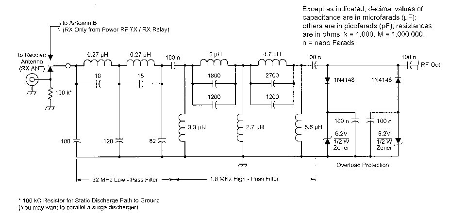
Fig 2 - A schematic of the high- and low-pass filters. The 100-kΩ resistor near the RX ANT connector provides a path to ground for electrostatic discharges.You may want to add a surge supressor in parallel with it.
Our Front End
Now, our accessory needs to be an external independent front-end unit with its own filtered power supply. It should be easily connected to any transceiver (new or old) with:
- A variable attenuator from 1 - 20 dB with a bypass switch;
- Modular ham-band-only band-pass filters with relay switching (no diodes to avoid IMD), the inputs of unused filters are shorted to ground;
- Two stages of preamplification;
- A push-pull, broadband medium quiescent-current amplifier configuration with low IMD and a reasonably low noise figure with some kind of RF feedback.
The variable attenuator and preamplifiers are protected by the band-pass filters, since they are placed after them in the receiver chain.
This is a reinterpretation of a highlevel receiver front end, as we see it, adapted for our use. lt is a system made with well-known circuits as building blocks. You can modify what you want, since every unit is modular. Improvements are welcome.
The unit must be capable of some switching among different antennas: ANT 1 RX/TX, ANT 2 RX/TX, RX-ONLY ANT. For each antenna selected, the receiveonly signal path is always routed through the band-pass filters. See K5AM's article (QEX, Nov/Dec 2001, p 40) in which he pointed out different IP2 performance when measured at the main receiver terminal or at ANT RX ONLY input, leaving some hope to the home builder for better performance.
The front end should be useful in casual DX operating, in single-operator contests and in multi-operator contests with the receiver signal parallel routed to two receivers. These would be a main receiver and a secondary receiver with a second operator who can tune independently. It should be capable of work in low-frequency amateur bands but with modular construction that can be upgraded to cover all HF bands including WARC bands.
When used with full-sized antennas, it should provide benefits as well, since the band-pass filters are designed and aligned with sharp bandwidth and excellent shape factor. We use more space than most embedded band-pass filters. Equipment manufacturers must tradeoff cost, dimensions and the Q of components.
I'm thinking now of an Amateur Radio system composed of one antenna with multiband coverage with only one feed line to the rig that covers 10, 15, 20, 40 meters and the WARC bands, like log-periodics. Friends with such antenna systems told me about more IMD problems in their receivers during evening hours because of the high-level signals present in the broadcast bands around 40 meters. The situation is a bit better for those who use monoband antennas and separate antennas with separate feed lines for 40 and 80 meters. Again, this problem seems to be worse in Europe, as pointed out by G3RZP.
Think about radios with receiver general-coverage capability. If the number of band-pass filters is 10, they must be around 3 MHz (30 MHz/10) wide at -3 dB, and of course much more at -60 dB. These so called "suboctave-width. band-pass filters" are a limited form of preselector filtering 17 but they are still helpful. We have tried to select band-pass filters with bandwidth of around 400 kHz, except on 28 MHz because the band we can use is 1.7 MHz wide. The filters are centered at the middle of each amateur band with an acceptable insertion loss. In that way, the improvement in bandwidth we achieve is about 6 to 1 (3 MHz/0.4 MHz) and we believe that everything before the first IF roofing filter is a bit better protected from strong, out-of-band signals.
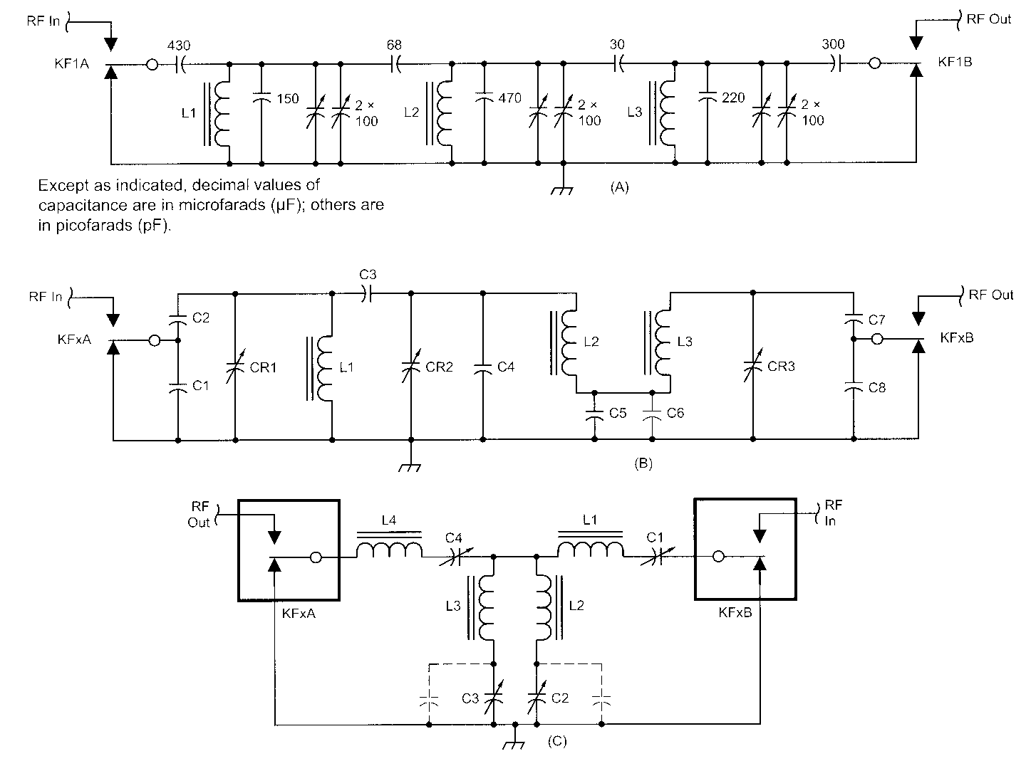
Fig 3 - Schematics of the band-pass filters. (A) shows a 1.8-MHz band-pass filter from an old Handbook. L1, L2 and L3 are T68-2 powdered-iron toroid cores with 40 turns of 0.5-mm (#24 AWG) enameled wire. Capacitors are dipped mica parts. Variabie capacitors are Philips film/Teflon units that are 10-mm in diameter. (B) shows 3.5 to 28 MHz Butterworth filters with inlout capacitive dividers. See Tabie 2 for each band's design values. Connect the relay 12-V control lines together, and control thern with circuit in Fig 1 B. Decouple the control lines for RF at both ends. (C) shows 3.5 to 28 MHz Cauer filters. See Table 3 for each band's design values.
| Band (MHz) | Toroidal cores L1-2-3 | Turns | Wire diameter (mm) | µH | C1-C8 (pF) | C2-C7 (pF) | C (pF) | C4 (pF) | C5 (pF) | CR1-2-3 Var. C. (pF) | CR var C (pF) |
|---|---|---|---|---|---|---|---|---|---|---|---|
| 1.83 | For 160 m data, see ARRL Handbook 1980 p. 8-43 and refer to our dedicated board. | ||||||||||
| 3.7 | T50-2 | 44 | .035 | 10 | 1000 | 150 | 5.6 | 150 | 10000 | 100 | 10 |
| 7.07 | T50-2 | 31 | 0.5 | 5 | 410 | 82 | 3.9 | 75 | 5000 | 65 | 10 |
| 10.1 | T50-2 | 24 | 0.6 | 2.8 | 300 | 68 | 3.3 | 56 | 2700 | 22 | 7 |
| 14.2 | T50-6 | 22 | 0.75 | 2 | 200 | 44 | 2.2 | 40 | 2400 | 22 | 7 |
| 18.1 | T50-6 | 20 | 0.8 | 1.6 | 150 | 33 | 1.5 | 33 | 1800 | 22 | 7 |
| 21.2 | T50-6 | 18 | 0.8 | 1.4 | 135 | 30 | 1.7 | 28 | 1250 | 22 | 7 |
| 24.9 | T50-6 | 16 | 0.8 | 1 | 120 | 27 | 1.5 | 22 | 1000 | 22 | 7 |
| 28.5 | T50-6 | 14 | 0.8 | 0.8 | 100 | 22 | 1.5 | 18 | 560 | 22 | 7 |
| L1-L4 | C1-C4 | L2 | L3 | C2 | C3 | ||||||||||||
|---|---|---|---|---|---|---|---|---|---|---|---|---|---|---|---|---|---|
| Band (MHz) | Core | Turns | Wire diam (mm) | µH | Var C (pF) | Core | Turns | Wire diam (mm) | µH | Core | Turns | Wire diam (mm) | µH | Var Cmax (pF) | Fixed C (pF) | Var Cmax (pF) | Fixed C (pF) |
| 28.5 | T80-6 | 34 | 0.75 | 6 | 1.5-5.5 | T50-10 | 10 | 0.75 | 0.3 | T50-10 | 0.75 | 0.75 | 0.2 | 100 | 56 | 65 | 56 |
| 24.9 | T80-6 | 36 | 0.75 | 6.8 | 1.5-5.5 | T50-10 | 11 | 0.75 | 0.4 | T50-10 | 10 | 0.75 | 0.3 | 100 | 68 | 100 | |
| 21.2 | T80-6 | 38 | 0.75 | 7.4 | 1.5-5.5 | T50-10 | 17 | 0.75 | 1 | T50-10 | 16 | 0.75 | 0.9 | 65 | 65 | ||
| 18.1 | T80-6 | 39 | 0.75 | 8 | 1.5-5.5 | T50-6 | 20 | 0.75 | 1.8 | T50-6 | 18 | 0.75 | 1.5 | 65 | 65 | ||
| 14.2 | T94-2 | 46 | 0.75 | 18 | 1.5-5.5 | T50-6 | 16 | 0.75 | 1.2 | T50-6 | 15 | 0.75 | 1.0 | 100 | 56 | 65 | 47 |
| 10.1 | T94-2 | 60 | 0.5 | 30 | 1.5-5.5 | T50-2 | 23 | 0.5 | 3.3 | T50-2 | 22 | 0.5 | 2.7 | 100 | 65 | ||
| 7.05 | T94-2 | 64 | 0.5 | 34 | 3-13 | T50-2 | 20 | 0.75 | 2 | T50-2 | 16 | 0.75 | 1.5 | 100 | 280 | 100 | 220 |
| 3.7 | T94-2 | 64 | 0.5 | 34 | 65 | T50-6 | 18 | 0.5 | 1.7 | T44-10 | 14 | 0.5 | 0.8 | 2200 | 1100 | ||
| 1.83 | T94-2 | 100 | 0.35 | 85 | 100 | T50-2 | 25 | 0.5 | 3.3 | T50-2 | 18 | 0.5 | 1.7 | 3900 | 2300 | ||
We have data for all nine amateur bands, WARC included, of two different band-pass filters types. First is the Butterworth response (Fig 3B, Table 2) with three toroidal inductors, based on a study previous published in QST by Bill Sabin, WOIYH. 18, 19 Second is the Cauer response with four toroidal inductors (Fig 3C, Table 3). Our Cauer (elliptical) is a little different from that presented in QEX by W3NQN.20 That version emphasized maximum attenuation in adjacent amateur bands. Ours is in the same family, but it is easier to wind the toroidal cores - on a single layer-since it is already calculated to match 50 Ω.
We found the initial idea and data for this version of Cauer filters from the 0K1RR Web site and we have verified them.21 We tried larger-diameter toroidal cores -T94 instead of T68- as was used by W3NQN in his version.
Our Cauer filters are optimized third-order ellipticals with steeper skirts than traditional Butterworths. We compared ours with three-toroidal-inductor Butterworth versions (Fig 4) and you can see the different shapes yourself with the following procedure.
We thank 0K1RR and W3NQN who first mentioned the ELSIE program to us in QEX. We would like to go further inside it with you and discover together how it is a friendly and powerful tool.
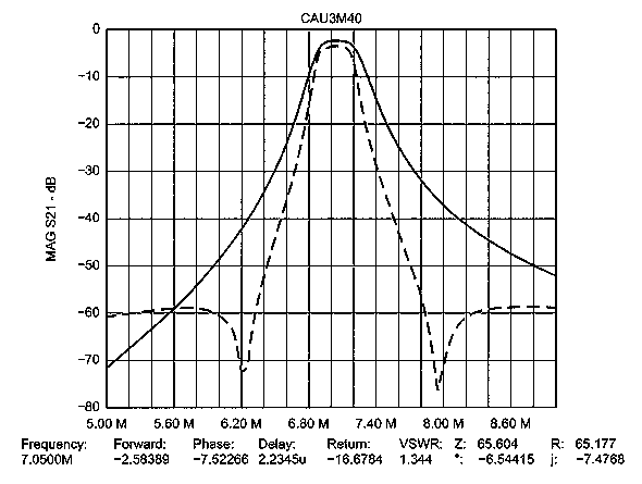
Fig 4 - Response curves for the Butterworth and Cauer band-pass filters.
ELSIE Software by WB6BLD for RF Filter Design
For both versions, we have winding data on Amidon toroidal cores. They may be analyzed with ELSIE 22 by WB6BLD, James Tonne, of Trinity Software, who now Iets you download freely a fully functional student/amateur version from his Web site. I would like to thank James for that-very well done.
You can easily superimpose three different curves, that is, 3-MHz normal filter bandwidth, the Butterworth and the Cauer (both with a sharper 3-dB bandwidth like 0.4 MHz), to see the different behaviors in shape factor. It is also easy to simulate changes in values with instant impact on the curve shown. And you can even print to an HP laser or compatible ink jet printer.
Download ELSIE software from WM6BLD's Web site. This demo version is fully working and the main limitation is the upper filter order of seven. You can store up to 15 work files in the same folder. To be able to recall some files for overlay purposes, keep the working files created and saved in the same folder. Move the ones you don't immediately need to another folder.
After you learn how to enter a filter design into ELSIE, you get a beautiful display of the filter's response. With relatively wide frequency spans, you see the filters behavior away from the passband. Change the frequency span to check more precisely the -6-dB bandwidth.
It is easier to do this at the computer than to explain the process here. The learning curve with this software is short, and it is as WB6BLD states: "After a bit, you will not need any manual". You have a lot more to see and discover with this software and you can print the output. A wonderful option is the capability to overlay more curves when you have already created all the files you want to compare. You can look at not only the transmission curve but also the return loss curve. The capability of fine-tuning the component values with real-time display of effects is amazing.
With all L-C data for the band of your interest, you need some help before starting to wind the toroidal inductors. You may need to go from one core size to another with some tradeoff in Q. I have recently found a very nice and useful Windows program, free, made by some Italian amateurs, IK2JSB and friends. It Iets you calculate simply the number of windings on most Amidon toroidal cores (you just select the type) from inductance value input. 1 remember a similar calculator in the well-known VE3ERP DOS suite of programs. Download the program from IK2JSB's site.23
When you run the program, choose option AMIDON. Some label descriptions about color codes for Amidon mixes are in ltalian, but it is very simple and complete.
Practical Considerations and Alignment Tips
Of course, you need to test and carefully tune each filter with small variable capacitors in parallel with the fixed values so the capacitances match the design data. We strongly suggest you use high-quality variable capacitors for easier alignment and the best filter shape. We used small Philips, Teflon-film, 300-V variable capacitors. For fixed capacitors, you can use ceramic disks; but we preferred the dipped-mica types.
Relaxed values of Q are realistic maybe 120 for Ls, 900 for Cs. We suggest you mount the series elements C1-L1 and L4-C4 first and check with a signal generator the insertion loss. If the attenuation is more than 10 dB, even with adjustment of the variable capacitors, you need to change the coil by one turn and try again. Then mount L2-C2 and L3-C3. Some fine-tuning of these values may be necessary for better shape factor and bandwidth settings versus attenuation. Check the whole filter shape and insertion loss. If you do not get top results in some higher bands, accept them or try a slightly wider bandwidth: 500 kHz to 1 MHz is normal. Again, some changes in L2-C2, L3-C3 may be necessary to trade off for better attenuation. In the lower microhenry values, the errors tend to be greater. So a core made from the winding by data can be quite far from the proper value. In the lower bands, the results we got are much closer to predictions.
We must report that in two or three bands we got some practical data that were a lot different from those reported by OK1RR; otherwise it couldn't work in practice. We use a small n attenuator to always get a proper 5U2 load.
All RF switching is done by simple small SPDT relays of reasonably good RF properties. Better ones have thick, gold-plated contacts; avoid palladium-alloy contacts. Precision inductance and capacitance meters might help. To get an idea about real performance, a network analyzer is the preferred instrument. Since most of us simply cannot afford one, I suggest you read the QEX article about RF network analyzers by Steve Hageman.24
Cauer filters seemed to work better when assembled on single-sided epoxy board for a bit less insertion loss. Butterworth seemed to work well also on double-sided copper epoxy board and they are easier to align.
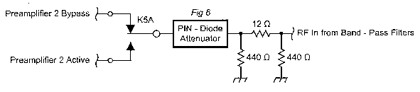
Fig 5 - Schematic of the preamplifier switching logic and matching.
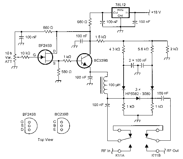
Fig 6-Schematic of the PIN-diode attenuator circuit. HP5082-3081 work better than those shown (see text). The board layout allows for an NAIS TX-2 12-V relay.
Variable Attenuator
Our attenuator has a variable 1-20 dB range with a panel-mounted resistive control. lt is built around traditional three-PIN-diode circuit (see Fig 6). It can easily be modified for automatie AGC for a receiver homebrew project. The most important thing is to select PIN diodes with minority carrier lifetimes longer than 1µs to improve IMD characteristics at low frequencies, as originally stated in HP Application Note 936 (now Agilent).
Suitable diodes in glass packages are the HP 5082-3080; or better, the 5082-3081 or MA47600. SMD versions are HSMP 3810; HSMP 3814 is a dual, common-cathode device. I suggest you read the very interesting HP/AGILENT Application Note 1048, "A Low-Cost Surface Mount PIN-Diode Π Attenuator", with schematies for a three-diode, 5082-3081 design with 15 V de attenuation control. There is a discussion about an even more symmetrical configuration with four diodes and a test report over the frequency range of 300 kHz to 3 GHz. At 10 MHz, a two-tone, third-order intermodulation distortion input intercept point over +30 dBm for attenuation settings in the range 10-20 dB is claimed. IP3 is better with less attenuation.
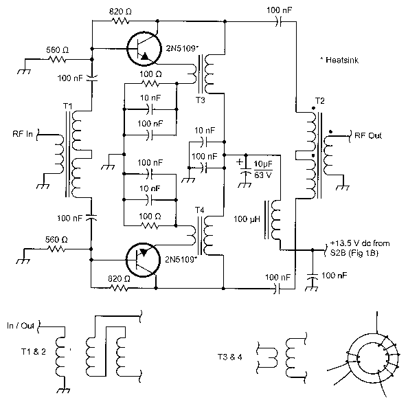
Fig 7 - Schernatic of the preamplifier circuit used in two stages. Tl and T2 are each 12 trifilar (twisted) turns of 0.35-mm (AWG #27) enameled wire on a Fr50-43 ferrite toroid core. T3 and T4 are each a 9-turn primary and a 2-turn secondary (0.35-mm AWG #27 enameled wire) on an FT37-43.
Push-Pull Broadband Preamplifiers
We have chosen medium-current 2N5109 RF transistors in a push-pull, common-emitter broadband configuration (see Fig 7). It is a low-noise version with transformer collector-emitter feedback and all home-built transformers. The basic design is from Ulrich Rohde, KA2WEU's artiele presented in ham radio magazine 27 (now available on CDROM from ARRL) with our own printed-circuit layout. In that article, there is also an IMD/dynamic range graphic as Fig 13, p 17, ham radio, Oct 1976. We have raised the quiescent current a bit (about 15 mA more) to 55-60 mA for each 2N5109, with our resistance value of 820 Ω from collector to base, for even less IMD. We measured OIP3 at around +41. Maybe we will achieve a slightly higher noise figure than the 2 dB indicated in that artiele. The rugged 2N5109s in TO-39 cases, with a rated power dissipation of 2.5 W, have performed very well with small heat sinks.
This preamplifier unit is simple, stable and reliable. We have had one in use since 1995 in 14FAF's homebrew HF transceiver front end for amateur bands only. There is a front-panel rig photo on our Web site; www.qsl.net/ik4auy/. We have had over 10,000 QSO's without any problem. Our rig architecture is triple-conversion with IF's at 10.7 MHz, 9 MHz with PBT and 455 kHz. We selected a Mini-Circuits highlevel passive doubly balanced mixer - a TAK-3H, +17-dBm LO-power unit with improved IMD (Level 17S) following our inside Butterworth band-pass filters.
We have two preamplifier units, so we can get 0/+10/+20 dB of gain if needed. The net gain depends on band-by-band filter insertion losses. Most of the time, I use only the first preamplifier stage. The gain per stage is around 12 dB. The sequence of our chain is shown in Fig 1. The filters are always in line in the receiver channel; then the variable attenuator if needed; then the amplifiers, if needed.
The unit includes a well-filtered power supply, with a small l-A ac RF filter, capable of delivering about 240 mA for the preamplifiers, switching relays and the variable attenuator (see Fig 9). A single metal LM317 is more than enough for very-long-time operations, mounted on the rear aluminum case of the unit with a mica insulator and silicon grease.
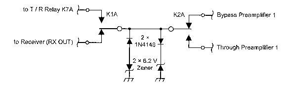
Fig 8 - Schematic of overload-protection and switching circuits.
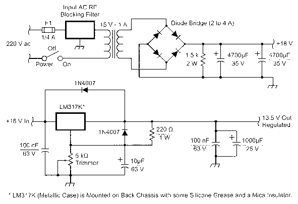
Fig 9 - Schematic of the regulated power supply. Although a 220-V ac input is shown, only the transformer need change for 120-V operation.
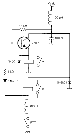
Fig 1O - Schematic of the PTT activated RF-power relay constructed from two reedrelays.
One more odd thing: ANT 1/ANT 2 and TX/RX channels input and output switching is obtained with three SPDT RF relays. Since we have a transmitter with maximum output of 120 W, we made our own SPDT relays with two SPST RF reed relays (see Fig 10), available at much lower cost than a good SPDT RF relay. They work very well and fast enough. For power levels up to 250 W, you can use any relay with contacts rated at more than 2 A and suitable for RF use. You might use surplus coaxial RF relays or a new Tohtsu CX120A (rated at 60 dB of isolation at 50 MHz in the RF PARTS catalog).
We used a 500-V dip-mica capacitor from the input of the last output relay to ground, around 30 pF to get an SWR very close to 1:1. Remember to check also, with a sensitive watt-meter to a dummy load, to avoid any dangerous RF coupling from the transmit antenna to the receiver antenna while transmitting.
Acknowledgement
This article is dedicated to my father, I4FAF, because it wouldn't have been possible without his valuable material work and many hours of bench tests.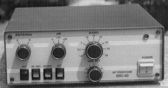
Fig 11 - A front view of the project.
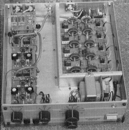
Fig 12 - (A) front-top view of the project.

Fig 12 - (B) rear-bottom view of the project.
Notes
- J. Devoldere, ON4UN, Low-Band Dxing, third edition (Newington, Connecticut: ARRL).
- J. Briggs, K1ZM, Dxing on the EDGE, (Newington: ARRL).
- E. Cunningham, K6SE, "Flags, Pennants and Other Ground independent Low band receiving Antennas", QST, Jul 2000, page 36.
- G. Breed, K9AY, "The K9AY Terminated Loop-A Compact, Directional Receiving Antenna", QST, Sep 1997, p 43. Hum problems when switching the K9AY loops (in QST Technical Correspondence).
- F. Koontz, WA2WVL, "Is this EWE for you?" QST, Feb 1995, p 31; feedback in Apr 1995, p 75.
- F. Koontz, WA2WVL, "More EWE for you", QST, Jan 1996, p 32.
- Antenna Compendium Vol. 5 (Newington: ARRL), "Ewe four me", by J. Smith, VK9NS, p 32.
- Visit www.contesting.com to get access to Top Band reflector.
- www.w8ji.com, Tom Rauch's personal Web site for receiving-antenna theory and ideas (see also four phased receiving only short vertical under "small-vertical arrays").
- K3KY Web-link collections about low-band receiving antennas (among them K6SE pennant, W7IUV rotatable pennant (www.qsl.net/w7iuv/), WA1ION variabie termination flag/pennant and more in www.qsl.net/wa1ion/).
- www.aytechnologies.com for K9AY loop info and distributed by ARRAY Solutions, www.arraysolutions.com, also www.hard-core-dx.com/nordicdx/antenna/index.html, antennas, choose loops.
- R. Brown, NM7M, "On the SSW Path and 160-meter Propagation", QEX, Nov/Dec 2000, pp 3-9; for top-band propagation characteristics.
- P. Marino, IT9ZGY, 1mpariamo a capire gli spot WWV", Radio Rivista (ARI), Jun 2001, p 47.
- E. Barbieri, I2BGL, "Il rumore atmosferico e l'ascolto ottimale dei segnali radio", part 2, Radio Rivista (ARI) Jun 2001, p 34.
- W. Sabin and E. Schoenike, HF Radio System & Circuits (Newington: ARRL, Order No. 7253).
- QST, Jul 2001, p 80: "Table 2-Dynamic Range Measurements at 5-kHz Spacing for Several Current HF Transceivers".
- W. Sabin and E. Schoenike, Single Sideband Systems and Circuits, second edition (New York: McGraw Hill) or the new edition in Note 15: W. D. Hart, Chapter 9 "Preselectors and Postselectors", p 359. "Sub-octave Bandpass Filter", p 357, summarizes the properties of preselectors in reducing: IM, cross-modulation, reciprocal mixing, desensitization, spurious and image responses and circuit overload damage.
- W. E. Sabin, W0IYH, "Design Narrow Band-Pass Filters with a BASIC Prograrn", QST, May 1983, pp 23 to 29.
- F. Cherubini, I0ZV, "Filtri preselettori per HF", Radio Rivista (ARI) Sep 1989, p 38, from 80 meters to 10 meters. A fine 160-meter band-pass filter from the 1980 ARRL Handbook, p 8-43. There are more tips about this front-end from Rockwell-Collins KMW-380 Service Manual.
- E Wetherhold, W3NQN, "Receiver Band-Pass Filter Having Maximum Attenuation in Adjacent Bands", QEX July/Aug 1999, pp 27-33.
- For the slightiy different Cauer band-pass filter to which we refer in this articie, see 0K1RR's Web site under "Tech Stuff, More front-end selectivity for your receiver". There, he also makes a comparative test with traditional weli-known W3LPL filters, originally presented by W3LPL, now at his Web site.
- WB6BLD ELSIE software at www.qsl.net/wb6bld/.
- IK2JSB has an Amidon toroidal coils calculator. Carefully follow the installation procedure described in the text.
- S.Hageman, "Build a 250 Mhz network analyzer", QEX, Mar/Apr 2002, pp 3-10.
- The idea to use an AD8307 as a logarithmic detector to show the filter curve on an oscilloscope occurred after the reading of W. Hayward, W7Z01, and R. Larkin, W7PUA, QST, Jun 2001, p 38 and W. Schneider, DJ8ES, "Logarithmic Amplifier up to 500 MHz with AD8307", in VHF Communications Feb 2000, pp 119-124.
- A very interesting application article "10.7 MHz, 120 dB Logarithmic Amplifier", by Barrie Gilbert, Eamon Nash, from Microwaves & RF for Mar 1998 is on-line in the Analog Devices Web site under Logarithmic Amplifiers technical articies. With an AD603 logarithmie variable amplifier in front of an AD8307, this one is a very fine upgrade for any oscilloscope display panadaptor project like that in QEX, May/June 1999, "A calibrated Panoramic Adapter", by Bob Dildine, W6FSH, pp 9-22, that uses a conversion architecture at 10.7 MHz IF.
- U. L. Rohde, DJ2LR (KA2WEU), "Optimum Design for High-Frequency Communications Receivers", Oct 1976 HAM Radio, p 10, includes a broadband HF preamplifier built around two CATV transistors on p 18, version C. ham radio is available on CD ROM from ARRL.
IK4AUY, ik4auy@arrl.net