Audio-modulated detection
An improved method for the reception of C.W. signals.
The most common present-day method of receiving keyed continuous-wave signals employs a beat-frequency r.f. oscillator which is tuned to within about 1000 cycles per second of the last intermediate-frequency signal and mixed with the latter in the second detector, thus producing an audio signal of about 1000 cycles per second, corresponding to the difference between the frequencies of the b.f.o. and the i.f. This arrangement has several disadvantages, among the more serious of which are the following:
- The components of noise signals present in the i.f. system also beat with the b.f.o. and thus cause a large increase in the receiver's noise level when the b.f.o. is functioning.
- There is an "audio image" signal created by any interfering signal which happens to be twice the audio beat away from the desired signal, and whose i.f. component is on the opposite side of the b.f.o. frequency from that of the i.f. component of the desired signal. This effect can be minimized by a highly-selective i.f. system, and by proper adjustment of the phasing control in the crystal filter.
- The tone frequency of the audio beat can not readily be held constant, because it depends directly on the frequency stabilities of the received signal, the receiver's high-frequency oscillator, and the b.f.o. itself. This inherent instability of the audio beat frequency is the reason that selective a.f. filters and reproducers have not found general favor in c.w. reception, in spite of the enormous advantages which such devices are recognized to have in the elimination of noise.
- The relatively pure tone of the audio beat quickly becomes fatiguing to the operator's ear. Numerous tests have shown conclusively that a tone rich in harmonics is much better for long periods of steady copying.
- Most operators set the b.f.o. to give a beat frequency near 1000 cycles. Although many operators would much prefer a lower frequency, such as 400 to 500 cycles, they usually listen to the higher frequency without stopping to wonder why they do so. The principal reason, of course, is tied up with the percentage drift of the audio beat. That is, a 200-cycle frequency drift from 400 cycles produces either 200 or 600 cycles a 2:1 or 1½:1 frequency change, which is inherently obnoxious to the average operator. The same 200-cycle shift from 1000 cycles, however, produces either 800 or 1200 cycles, a much smaller percentage change.
The authors have recently developed a new method of modulating a received c.w. signal which either eliminates or greatly minimizes every one of the foregoing objections to the b.f.o. and in addition provides positive audio a.v.c. The new system is called Audio-Modulated Detection, or A.M.D. for convenience of reference. The outstanding performance characteristics of A.M.D. are as follows:
- Provided a signal/noise ratio of 200/1 or better in tests made with about 0.6-microvolt input at 4.6 Mc., using a standard SX-28 Hallicrafters receiver in conjunction with an A.M.D. adapter unit. This compares with a signal/noise ratio of about 8/1 with the b.f.o. and the same signal.
- Delivers a constant audio-tone frequency for all signals, and thus makes practicable the use of a highly-selective audio filter of the electrical and/or mechanical type.
- Provides a choice of audio tone so that aural fatigue of human operators can be minimized.
- Provides automatic noise reduction on large noise peaks and substantially eliminates all sustained residual noises having small peak values.
- Provides audio-signal limiting at almost any desired output-voltage level, over a tremendous r.f. input-signal range (100,000/1 or better). Effectively, this feature tends to eliminate fading of the received signal so that it does for code reception what a.v.c. does for radiotelephone signals.
- Modulates weak and strong signals alike, whereas it is well known that the amplitude of i.f. signal voltage which will provide a good beat note when mixed with a fixed amount of b.f.o. voltage is definitely limited. This feature eliminates the necessity for constantly changing the r.f.-gain setting when the receiver is tuned from a weak signal to a strong one, and vice versa.
- Provides for the first time true single-signal reception, thus increasing the adjacent-channel selectivity of the receiver without the necessity for "diddling" with the crystal-phasing control in search of the zero-response notch. In fact, with A.M.D. the panel control for crystal-phasing can be discarded.
- Can readily be adapted to any existing communications receiver which employs a diode final detector, by means of a simple adapter unit located outside the receiver. For example, a selfpowered A.M.D. adapter has been constructed so that it can quickly be attached to an SX-28 without soldering or unsoldering a single wire in the receiver. The "conversion" to A.M.D. can be made in about two minutes.
Theory of operation
A simple diode-detector circuit is shown in Fig. 1. The theory of the circuit's operation is too well known to justify much discussion. Suffice to say that the diode rectifies the positive half-cycles of the i.f. signal voltage and thus, under steady-signal conditions, causes an average d.c. current I to flow through diode load resistor R in the direction indicated.
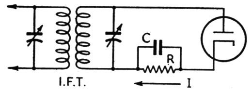
Fig. 1. Simple diode-detector circuit.
If we now connect another diode (2) in parallel with detector diode (1), but reversed, as shown in Fig. 2-A, it is apparent that diode 2 will rectify the negative half-cycles of the i.f. signal voltage, thus producing an average d.c. current I2 which flows through resistor R in the opposite direction to current I1, but practically equal to I1 in amplitude. Thus, the two equal-and-opposite average d.c. currents cancel each other, with the result that no signal voltage is built up across R. Operational diagram Fig. 2-B shows what happens.
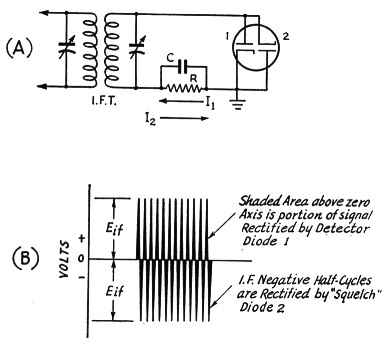
Fig. 2. (A) Diode detector (1) with reversed diode (2) connected as a "squelcher." No signal voltage is built up across R because I2 cancels I1.
(B) Operational diagram showing how the rectified currents of each of the M, 9 djock, 1p (A) cancel each other.
We now proceed to insert battery E.e, as shown in Fig. 3-A, with its negative terminal facing the anode of diode 2. This battery provides a delay bias on diode 2 so that it will not rectify negative half-cycles of the i.f. signal voltage until their peak-voltage value exceeds the d.c. voltage of battery Esd. For small signals, therefore, diode 1 goes right on rectifying the positive half-cycles of i.f. voltage just as if diode 2 did not exist. Fig. 3-B helps to explain the operation.
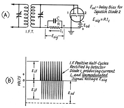
Fig. 3. (A) Same as Fig. 2-A but with d.c. delay-bias Esd added to squelch-diode 2 only.
(B) Operational diagram showing how squelch-diode 2 is prevented from rectifying the i.f. negative half-cycles so long as Esd is larger than Eif
This procedure again gives us a d.c. signal voltage across R, but still no audio modulation. To obtain that, we obviously must vary or modulate the delay bias applied to diode 2 so that the latter alternately squelches and unsquelches, at an audio rate, the signal current produced in R by diode 1. To accomplish this modulation of the squelch-diode delay bias, we employ the circuit of Fig. 4-A, which is probably the simplest form of A.M.D.
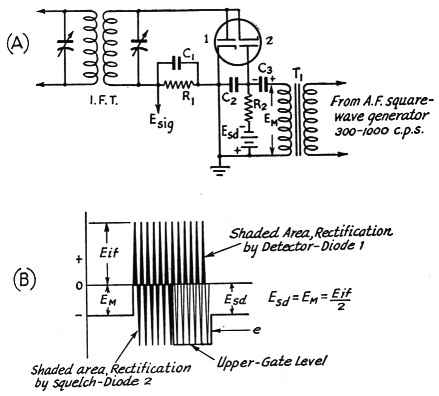
Fig. 4. (A) Basic single-gate A.M.D. circuit.
(B) D.c. delay bias on squelch-diode 2 is modulated by local a.f. voltage EM, thus modulating the signal practically 100 per cent. Eif = peak i.f. signal voltage; EM = peak a.f. modulating voltage; Esd = squelch-diode d.c. delay bias; e = squelch-diode instantaneous delay bias.
The operation of this circuit can readily be understood by reference to Fig. 4-B. From an inspection of this diagram we can see that we not only get a.f. modulation of the i.f. signal at whatever tone frequency we desire to inject, but also that we have established an "upper gate" which limits any i.f. signal or i.f. noise component whose peak amplitude exceeds the upper-gate limit.
This i.f. limiting does two things, both highly desirable. It effectively squelches all noise peaks above the predetermined upper-gate level, and it also puts a definite audio-volume "ceiling" on the received signal. An "S9-plus" signal which greatly exceeds the upper-gate level produces exactly the same headphone volume as an "S2" signal (for example) which just reaches the upper-gate level. This feature of A.M.D. not only greatly improves the signal-noise ratio but also completely eliminates fading over an input-signal range of better than 100,000 to 1 (100 dB). Another inspection of Fig. 4-B shows that noise is further reduced by the fact that 100 per cent squelching occurs on each positive half-cycle of the audio modulating voltage - i.e., for approximately half the time - provided that the voltage has a symmetrical square-wave form. This squelching action cuts even the sustained low-level noises exactly in half. In a conventional receiver, these noises are actually amplified in magnitude when the b.f.o. is turned on.
The next logical step, of course, is the placing of a delay or "threshold" bias on the detector diode. Such a bias enables us to eliminate the low-level residual-noise voltages which usually buzz merrily along when the receiver is operated at maximum gain, even in a very quiet receiving location. This delay bias, Edd, can be inserted as shown in Fig. 5-A. This circuit shows the "Double-Gate A.M.D." system, and works as indicated in operational diagram Fig. 5-B. With this arrangement, very small i.f.-signal and i.f.-noise components are not modulated because their amplitude is less than d.c. delay-bias Edd. Thus, the receiver actually sounds completely "dead" until a signal or noise appears whose peak i.f. amplitude exceeds the voltage Edd. In a manner of speaking, the small noises are cut out from under the useful portion of the desired signal and the high-amplitude noise peaks are neatly clipped at any desired upper-gate level which does not result in excessive signal-peak clipping.
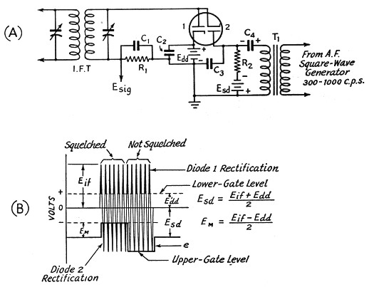
Fig. 5. (A) Basic double-gate A.M.D. circuit.
(B) That portion of the signal represented by Eif - Edd is fully modulated by EM.
Eif = peak i.f. voltage;
E'dd = detector threshold level (lower gate);
EM = peak a.f. modulating voltage;
Esd = squelch-diode d.c. delay bias;
Edd = detector-diode d.c. delay bias (= E'dd);
e = squelch-diode instantaneous delay bias.
Inasmuch as the locally-generated audio tone frequency can easily be held to a fixed value, A.M.D. makes practicable the use of a highly-selective a.f. filter in the output system of the receiver. This a.f. filter should be of the band-pass type having a pass-band of 20 cycles or more, depending on the maximum keying speed it is desired to pass. If the pass-band is too narrow (say 10 or 15 cycles), high-speed keying will not be faithfully reproduced, because the dots and dashes will have pronounced "tails." A 400-cycle band-pass filter (consisting of three LC sections) having a pass-band 180 cycles wide at 5 dB down, and being down at least 40 dB at 200 and 1000 cycles, respectively, has been found to give extremely good results.
Tests with a double-gate A.M.D. adapter attached to a Hallicrafters SX-28 receiver were made at 4.6 Mc. with a 0.6-microvolt input signal. With the LC audio output filter mentioned above, a signal-plus-noise to noise ratio of better than 200 to 1 was easily obtained, with a.f. and r.f. receiver gain controls at maximum. With the conventional b.f.o. method of reception, the best signal-plus-noise to noise ratio that could be obtained was about 8.
The selective a.f. filter accounts for much of the improved signal/noise ratio obtainable with A.M.D. It is not practicable to use such a filter with the b.f.o. method of reception, because the audio beat frequency varies with every slight change in the frequency of the transmitter, of the receiver's high-frequency oscillator, and of the b.f.o.
There are four types of selectivity which can be employed in a c.w. telegraph receiver, as follows:
- R.f. and i.f. (tuned circuits, quartz-crystal filters)
- Electrical a.f. (band-pass filter)
- Mechanical a.f. (resonant reproducer)
- Aural (the human ear)
With the first three types, the only limit is the width of the pass-band required to pass the modulation component of the r.f. signal, which is a function of the keying speed. The significance of this statement can perhaps better be understood when we put it this way: with A.M.D. and a highly-selective receiver, it is possible to separate completely two signals which are only 20 cycles apart and yet modulate either at any desired audio frequency. This would not be possible, of course, with the b.f.o. With A.M.D., there can be no audio-image interference and true single-signal reception in the fullest meaning of the term is achieved.
The A.M.D. adapter previously mentioned has several desirable features. It provides a continuously-variable audio tone from 330 to 1150 cycles, adjustable upper-gate and lower-gate bias voltages, adjustable square-wave modulating voltage, and an unique type of selective filter developed especially for use with A.M.D. This unit will be described in a subsequent issue of QST.
D.A. Griffin, W2AOE
L.C. Waller, W2BRO.