Preventing self-oscillation in tetrode amplifiers
Cathode followers as drivers for beam tubes.
Here is a step in the right direction toward taming wild or even housebroken tetrode amplifiers. One way, of course, is to neutralize the beastie, but W9ECO uses another approach which shows considerable promise when handled properly.
Anyone who has tried to operate a tetrode at the higher frequencies must wonder why the claim "neutralization usually unnecessary" doesn't read "neutralization unusually necessary"!
It is an accepted fact that the grid-to-plate capacitance, though small, is the chief cause of instability in tetrode amplifiers, especially at the higher frequencies. This small capacitance feeds energy from the plate circuit back to the grid circuit and can readily set up oscillations of the tuned-grid tuned-plate variety, because of the high gain of the tubes. To stabilize such an amplifier, it is necessary to prevent this fed-back energy from setting up any voltage in the grid circuit. There are two ways of doing this: to neutralize, or to short the grid to cathode. The first method is well known, but neutralization of tetrodes is sometimes difficult because of the small value of capacitance involved, and many of the advantages of the tetrode are lost if the circuit is complicated by neutralizing. The second method introduces the problem of exciting the grid and at the same time shorting it to the cathode. Although this may seem paradoxical to the uninitiated, the solution is to use a zero-impedance generator. Fig. 1 shows the basic circuit of a tetrode amplifier drawn in two different ways, and it is obvious from Fig. 1-B how effectively the theoretical Zg = 0 shorts the grid. In practice, however, it is impossible to find a generator of zero impedance, but fortunately when a cathode-follower driver is used, then Zg will be equivalent to only a few hundred ohms.(1) If Zgp is many times this value, the resultant voltage division is practically the same as if a zero-impedance generator were used.
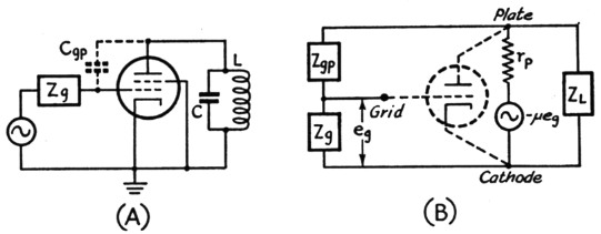
Fig. 1. The simplified diagram of a tetrode amplifier is shown at (A). The grid circuit is represented by a generator and an impedance Zg. The diagram in (B) shows another way of drawing the circuit to illustrate feed-back from the plate circuit of the tube through the grid-plate capacity (represented by Zgp). The tube has been replaced by its equivalent diagram and the plate load is represented by ZL. Note that Zs and Zgp form a voltage divider, and that the voltage developed at the grid is proportional to the ratio of Zg to (Zgp + Zg). Obviously if Zg is very small or zero, there will be little or no voltage developed from grid to cathode.
A good way to evaluate the effectiveness in preventing oscillation of the low Zg presented by a cathode-follower driver is to use the equation quoted on Page 112 of June QST, which can be rearranged to state that the maximum Rg (Zg) a tube can have without oscillating is
where
τp = plate resistance of tube
μ = amplification factor of tube
RL = plate-tank impedance at resonance
Rg = Zg = shunt grid impedance
Cgp = grid-plate capacitance of tube
f = frequency
rp = 0.1 megohm,
μ = 600,
RL = 50,000 ohms (unloaded tank impedance),
Cgp = 0.2 µµfd. max.,
Rg = Zg presented by 6V6 cathode follower and
f = 30 Mc.
Substituting in (1) above, Rg = 265, and hence Zg must be greater than 265 ohms for the 807 to oscillate. Since it is practicable to build a 6V6 cathode-follower driver which presents a Zg of less than 265 ohms, the 807 will definitely not oscillate.
When RL is 3000 ohms, corresponding to a loaded tank circuit, Zg can be as high as 3035 ohms before oscillations begin, and, since the Zg is less than 265 ohms, a large margin of safety exists.
Cathode-follower drivers
When considering a cathode follower as a driver, the following must be known:
- Cgp of tube to be excited.
- Zg presented by the cathode follower.
- Total shunt capacitance in the cathode-follower cathode circuit.
- Peak grid swing required for the excited tube.
- Grid-drive power required for the excited tube.
Items 1 and 2, used in conjunction with the equation discussed above, determine the maximum frequency at which the cathode follower will prevent oscillations. In Item 2
![]()
where gm is the mutual conductance of the follower. Item 3 will determine the maximum frequency at which useful power can still be obtained from the cathode follower. Suppose, for instance, the total cathode shunt capacitance is 30 pF. At 28 Mc. this represents approximately 200 ohms and is not a good load for a follower to work into. But by resonating this capacitance in parallel with 200 ohms of inductive reactance having a Q of 200, the load into which the follower will work will be 40,000 ohms in parallel with the resistance load of the amplifier grid (about 20,000 ohms for the 807), and the resultant 13,330-ohm load is quite adequate.
Items 4 and 5 will determine the type of cathode follower to use and how much d.c. power it will need. For example, from published characteristics, an 807 requires a peak grid swing of approximately 115 volts, with approximately 0.4 watt of grid-drive power. One half of a 6SN7GT, operating as a Class A cathode follower with a d.c. input of 3 watts (300 volts at 10 mA) is capable of a little better than 115 peak volts and about ¾ watt output; its efficiency is 25 per cent and the Zg it presents to the 807 is about 400 ohms. The grid-drive power required by the follower is negligible, since the grid does not draw current. All that is needed is voltage swing (approximately 120 peak volts). A quadrupler should therefore work nicely into the cathode-follower grid.
If more voltage swing and power output are needed, perhaps to drive an 813, a 6V6 tetrodeoperated cathode follower will give about 200 peak volts and approximately 4.5 watts output, with 12.5 watts input (250 volts at 50 mA). It will have a plate efficiency of 36 per cent and will:present a Zg of 250 ohms.
In my own case, after prolonged testing of the 6V6 and 6SN7GT for driving an 807 rig, I finally settled on the 6SN7GT because one section could be used as a doubler and the other section as the cathode-follower driver, thus cutting down the number of tube envelopes as well as the amount of d.c. power required.
The 6V6 has reserve excitation, while the 6SN7GT has only just enough power output to drive the 807 for phone operation, or twice the grid drive needed for c.w. All these measurements were made at 30 Mc., which is about the upper limit for the 6SN7GT as a cathode follower. Although no difficulty should be encountered at 14 Mc., satisfactory operation at 50 Mc. might be hard to obtain.
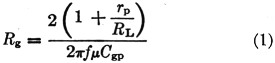
At present my rig has the following tube lineup: 6SJ7 ECO; half of a 6SN7GT, doubler; half of a 6SN7GT, cathode-follower driver; and an 807 final amplifier. The circuit is shown in Fig. 2.
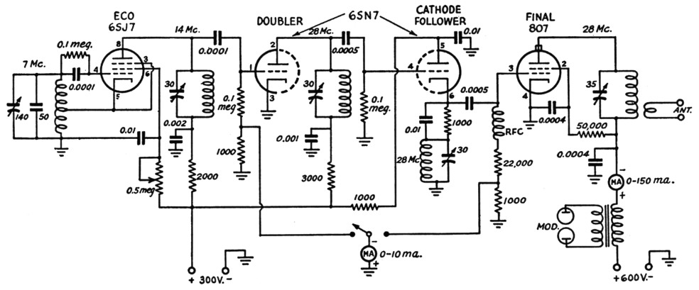
Fig. 2. The author's 28-Mc. transmitter, illustrating the application of the cathode-followerdriver.
A tetrode can be used as a cathode-follower driver, as shown in Fig. 3. Note that the screen grid is tied to the cathode through a large condenser, and the screen voltage is fed from the plate through an r.f. choke. Otherwise the circuit and operation are similar to a triode-follower circuit.
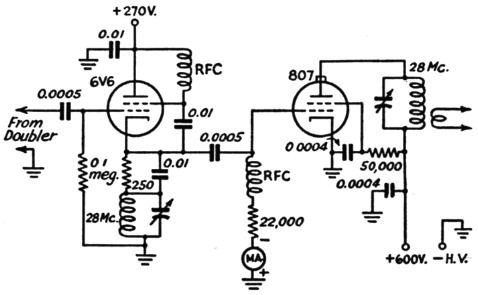
Fig. 3. A 6V6 or other tetrode can be used as a cathode-follower driver where more drive is required.
There are no tricks to the tuning procedure, but it must be accurate, as mentioned later. In Fig. 2, the 14-Me. tank circuit is tuned by adjusting for maximum grid current in the 6SN7GT doubler, and then the doubler plate circuit and the follower cathode circuit are tuned for maximum grid current to the 807, about 4 mA. It will be found possible to obtain a set of conditions where the follower willact as an ultraudion oscillator, but this is not the case when the cathode and grid circuits are tuned to exact resonance. If the grid circuit is tuned off to the high-frequency side or if the cathode circuit is detuned to a lower frequency, self-oscillation will probably start. However, if the grid current of the 807 falls to zero when the VFO is turned off, it indicates a stable condition of the cathode-follower stage. The final plate voltage is then turned on and the output circuit tuned for a dip in the usual manner.
For proper operation of the cathode-follower driver, observing the following precautions should keep pne safely out of trouble: First, the magnetic coupling between the doubler tank and the follower tank should be held to a minimum, to avoid the possibility of oscillation in the cathode-follower stage. Small-diameter coils mounted at right angles and separated by several coil diameters will do the trick. Secondly, the final tank should be isolated from all other tuned circuits by placing it above the chassis and keeping the other circuits below the chassis. This is the usual precaution of minimizing the magnetic coupling between plate and grid circuits.
If the oscillator in Fig. 2 is to be keyed for break-in -operation, several changes must be made. First, Ehe ECO should be replaced by one that keys well, or by a crystal oscillator. Second, protective bias must be added to the doubler by using battery bias (22.5 volt). Next, the Class A cathode follower must be left running all of the time, but make sure the doubler plate and cathode-follower cathode circuits are tuned to the same frequency, as mentioned previously. A 15,000 ohm dropping resistor should be used between plate and screen of the 807, with a 20,000 ohm bleed from screen to ground. About 45 volt of fixed grid bias should be added to the 807, to limit the current under key-up conditions. This will not be enough to cut off the plate current when the key is up, but more isn't necessary because the 807 won't oscillate, no matter where you set the plate tuning!
Notes
Paul D. Prelim, W9ECO.