Impedance matching with an antenna tuner
The link-coupled antenna tuner shown in Fig. 1 is a useful device because it not only provides needed selectivity for preventing transfer of harmonics to the antenna but offers a means for obtaining symmetrical coupling between a single-ended tank circuit and a balanced feeder system. It is also commonly regarded as a means for matching the impedance of the feeder to the required transmitter load, the theory being that the load is adjusted by changing the spread between the feeder taps on L2 and the coupling between either or both of the two tank coils and their associated link coils, L2 and L4. When the transmission line is matched to the antenna so that the standing-wave ratio is near unity - that is, when the line is flat - the matching is relatively simple. However, it doesn't always work out so nicely when a resonant line is used. On occas ons it proves to be difficult, if not impossible, to load up the final stage; tuning is sluggish; part or all of the antenna tank coil, L2, heats; and results generally are unsatisfactory.
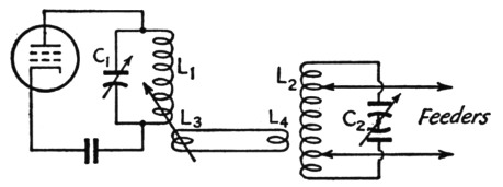
Fig. 1. The link-coupled "universal" antenna coupler.
It is common knowledge that a transmission line terminated in a resistive load equal to its characteristic impedance can be any length and the impedance looking into the sending end always will be a pure resistance equal to the line impedance. But if the load has any other value the impedance looking into the sending end will be complex - that is, it will have both resistive and reactive components. The magnitudes of both components will depend upon the electrical length of the line, the characteristics of the load, and the characteristic impedance of the line itself. Matching the transmitter to the input end of such a line entails two separate operations: (1) "tuning out" the input reactance by supplying an equal amount of reactance of the opposite kind, and (2) adjusting the coupling so that the desired power is transferred to the resulting purely-resistive component of the line's input impedance.
In the coupling circuit of Fig. 1, a resistive load readily can be matched to the transmitter by changing the spread between the taps on L2. When the line has reactance as well as resistance the reactive component is reflected across the whole tank in proportion to the ratio of the impedance, as measured across the ends of the tank, to the impedance of the load between the taps. Since the taps generally are not at the extreme ends of L2, the reactance reflected across the tank as a whole is usually higher than the reactance of the line. The reflected reactance is equivalent to an inductance or capacitance (depending upon whether the line is inductive or capacitive) shunting the whole circuit. The circuit is consequently detuned, and C2 is supposed to be readjusted to resonate it.
To a limited extent, this scheme for tuning out the line reactance will work quite satisfactorily. It is at its best when the reactive component of the line's input impedance is small compared to the resistive component. However, when the line reactance is comparable to or larger than the resistance, the circuit is at a disadvantage because it is inherently incapable of making the line itself "look like" a resistance. As an example, suppose that in Fig. 2 X and R in series represent the input impedance of the line, X being the inductive reactance and R the resistance, and that X is five times as large as R. (This is by no means an extreme case.) The line impedance, Z, is equal to √(X2 + R2), or 5.1 times the resistance. In order to supply a given amount of power to R we need a definite value of current through it, and this in turn means that there will be a definite voltage drop across R. But to get the desired current through R it is necessary to supply 5.1 times as much voltage to X and R in series as R alone requires.
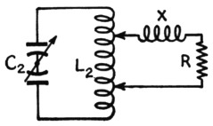
Fig. 2. Except at voltage and current nodes, the input impedance of a transmission line with standing waves can be represented by a reactance in series with a resistance. In this drawing the reactance, X, is assumed to be inductive.
The only way to get the larger voltage is to use more spread between the taps on L2 than would be necessary if the circuit were working into R alone as a load. But as the taps are moved farther apart the reactance reflected across the tank decreases. In the example of Fig. 2, moving the taps apart would be equivalent to shunting L2 with a coil of increasingly smaller inductance. Consequently, reresonating the circuit in such a case requires increasingly larger values of capacitance at C2, and it is not unusual to find cases where the resonance point is thrown completely off the condenser scale. If additional shunting capacitance is used and a working adjustment finally achieved, the common result is that the L/C ratio is so low that the circulating current becomes undesirably high and the sections of L2 between the taps and the outer ends get hot. The inner section may remain cool, since the current is divided between it and the line. When the line reactance is capacitive rather than inductive the story is much the same, except that in that case it may be necessary to operate C2 at minimum capacitance and reduce the inductance of L2 until it is possible to find resonance.
When difficulties of this sort are encountered normal operation can be restored by confining the function of the taps on L2 to matching to the resistive component of the feeder input impedance and making the reactance cancellation a separate operation. The process is simple and has the single disadvantage that an additional coil or condenser is required. The problem, if it can be called such, of tuning out the reactance component is simply that of shunting an appropriate amount of reactance, but of the opposite kind, across the input terminals of the line. It isn't necessary to make any calculations; the whole thing can be done by a simple cut-and-try process. Fig. 3 shows the circuits, A being for the case where the feeder has capacitive reactance, B for a feeder showing inductive reactance at its input end.
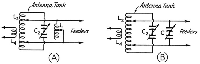
Fig. 3. Compensating reactances connected across the input terminals of the transmission line to tune out the line reactance. When a condenser, C, is required it need not be the balanced type shown, particularly when the larger values of capacitance are needed. However, the balanced type is preferable for maintaining symmetry.
To tune up the system, first disconnect the feeder taps from L2, loosen the coupling as much as possible, and tune C2 to resonance as indicated by a kick in the current of the plate tank, L1C1 being adjusted for minimum plate current as usual. In effect, L2C2 is being used as a wave-meter and the plate-current kick should be quite small. There is considerable danger here of using too much coupling, which will show up as a reaction on the tuning of the amplifier tank. The coupling should be so loose that C1 does not require readjustment for minimum plate current when C2 is brought to resonance. Note the resonance setting on C2's dial.
Next, tap the feeders on L2, using a small number of turns for a starter. Retune C2 to determine whether more or less capacitance is required to bring the circuit to resonance. If the capacitance must be increased the feeders are inductive and a compensating condenser, Fig. 3-B, must be used; if less capacitance is required at C2 the feeders are capacitive and Fig. 3-A applies. Let us assume that a compensating condenser, C, is required. Connect it as shown, reset C2 to the resonance point determined without the feeders connected, and adjust C until the whole system is resonant as indicated by the kick in final plate current. It should now be possible to connect or disconnect the feeders from L2 without changing the tuning of the L2C2 circuit. That's all there is to tuning out the feeder reactance. In case an inductance, L, is required, the process is the same, the most convenient arrangement being a coil that can be tapped at every turn.
The next step is to match the resistive component of the line to the transmitter. As the spread between taps is increased, the load on L2C2 becomes greater and the resulting decrease in the Q of the circuit makes it necessary to use closer coupling between L1C1 and L2C2. It should be possible to find several combinations of tap spread and coupling that will load the final amplifier to rated plate current. However, it is advisable to use that combination that gives the proper loading with relatively loose coupling, since loose coupling means less harmonic transfer. When the coupler is working properly, detuning C2 to either side of resonance should cause the final plate current to decrease - a distinctly advantageous feature of this type of antenna tuner in that accidental detuning in the antenna system will not overload the amplifier.
How much L or C will be required depends on the line length, the characteristic impedance of the line, and the standing-wave ratio. In general, excessively large condensers or coils will not be necessary. The worst cases in this respect occur at certain line lengths with high standing-wave ratios and low-impedance feeders. Fig. 4 gives the minimum required shunt reactance in terms of a factor to be applied to the characteristic impedance of the line. For example, if the standing-wave ratio is 10-to-1 on a 600 ohm line the minimum reactance required for the worst case is 0.22 × 600 - 132 ohms, or if the standing-wave ratio is 2-to-1 on a 70 ohm line the minimum reactance required is 1.05 × 70 = 73.5 ohms. The latter case corresponds to a condenser of about 500 pF at 4 Mc, and considering the ways in which high- and low-impedance lines are used it does not seem likely that a larger condenser would ordinarily be needed. In most cases much smaller values will be called for. Very high values of shunt reactance need not be used (that is, very large coils or very small condensers) because in such cases the reactive component of the line's input impedance is small and the ordinary coupler alone is capable of handling the situation.
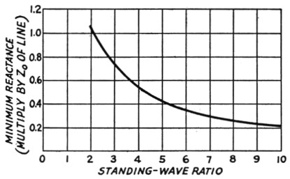
Fig. 4. Minimum values of reactance required by the circuits of Fig. 3 as a function of standing-wave ratio and line characteristic impedance. For any particular frequency the reactance may be converted into inductance or capacitance by the formulas or charts given in the ARRL Handbook. With standing-wave ratios higher than 10, the minimum reactance required is very nearly equal to twice the characteristic impedance of the line divided by the standing-wave ratio.
The compensating reactance need not be used, of course, unless poor performance of the coupler by itself requires it. When it is used, it is generally not necessary to readjust it for working through a band, provided it is adjusted for a frequency near the center. Minor departures from the pure-resistance load condition can be taken care of by C2. There may be exceptions to this in the case of long lines with high standing-wave ratios, but usually the reactance can be set at a median value for each band and left alone.