Let's not overmodulate - It isn't necessary!
Speech clipping and filtering for more effective communication.
Crank up the gain and blast that DX loose - and still be looked upon kindly by the fellows on the next channel because they don't have to swallow your overmodulation splatter! That's what a clipper-filter in the audio system can do for you. Here's more practical information on a principle introduced in QST last winter.
High average modulation is most desirable in radiotelephone communication, in order to be heard above static and QRM at the receiving end. Yet in a carrier modulated 100 per cent on voice peaks, the average modulation is roughly 30 per cent. A common method of improving the situation is to crank up the audio. The result is, of course, lots of audio. Also over-modulation, a broad signal, splatter, loss of reputation, and violation of the FCC rules and regulations for amateurs. On the other hand, it's downright irritating to get a report that "you've got a strong carrier but the modulation's down," when you're using an oscilloscope and it says you have 100-per-cent modulation.
Many amateurs have used volume compressors to good advantage in obtaining higher modulation without splatter. Low-pass and band-pass filters have also been employed to limit the bandwidth to the range required for most effective communication. However, low-pass or band-pass filters do not eliminate any of the bad results of overmodulation; they only limit the frequency response of the audio system to the desired frequency range. They cannot prevent a broad signal or splatter when it is created in the final r.f. power amplifier because of overmodulation.
During the recent war the advantages of speech clipping were reaffirmed as a means of preventing overmodulation, with the added benefit of a high average audio level. Various authors have discussed it in more or less detail.(1) This discussion will present the matter in a practical manner, and will include circuits and data helpful to the person who would like to incorporate speech clipping in his audio amplifier.
The clipper is an instantaneous device. It is inoperative until the audio voltage reaches a predetermined level, then chops off everything above that level. As soon as the signal voltage drops below this limit the clipper ceases to operate. Such a device introduces a considerable amount of distortion, but the distortion is introduced at a point where the objectionable high-frequency harmonics can be controlled and not allowed to appear in the sidebands.
With average modulation of 30 per cent, the sideband power is down about 10.5 dB from the 100-per-cent level. If we should attenuate the voice peaks 10.5 dB and increase the over-all amplifier gain by the same amount, the lower-level voice components would be better utilized and the average modulation would approach 100 per cent.
In tests conducted for the purpose of determining the effects of harmonic distortion upon the intelligibility of speech, it has been established that the vowel sounds contain the major portion of speech power, yet contribute very little to intelligibility. Consonant sounds (t, k, c, p, y, b, etc.) carry little power but are the principal means of conveying intelligence. Therefore it should be possible to change or distort the wave-shape of the vowel sounds (the voice peaks) without adversely affecting intelligibility.
Extensive tests to determine the degree to which voice peaks can be distorted without adversely affecting intelligibility show that 6 dB of peak clipping is barely noticeable, 12 dB is not objectionable, and 24 dB of clipping can be tolerated. By the use of this system, and with an over-all increase in amplifier gain, (1) the effective power in the consonant sounds (low level components) is increased, (2) the mean audio power is increased, (3) the average modulation level is increased, (4) intelligibility is aided in QRN and QRM, and (5) the carrier is utilized to the maximum.
Circuit considerations
There are several methods of accomplishing peak clapping. An audio filter should be used in conjunction with a clipper to suppress high harmonics created by the clipping action and thus maintain a narrow bandwidth. The filter introduces problems of its own, but if clipping is done at a low level the filter components will be small and relatively inexpensive.
Fig. 1 shows the schematic of a simple peak clipper for use in a low-level Class A audio amplifier. R1 and R2 are each equal in value to the normal. cathode bias resistance for the particular tube. Potentiometers are used to vary the diode bias according to the signal amplitude at which clipping is desired. The 0.1-megohm resistor provides a high circuit impedance which is desirable with the shunt-type clipper shown in Fig. 1.
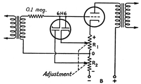
Fig. 1. A simple shunt-diode type peak limiter for low-level Class A amplifiers.
It can be argued that shunt clippers will not positively prevent overmodulation because the diode impedance does not drop to zero during conduction. However, in a circuit having an impedance of the order of 0.1 megohm, the somewhat-less-than-1000 ohms shown by the 6H6 is for all practical purposes a short-circuit. Fig. 2-A is a photograph of the output oscilloscope pattern of a normal modulator, and Fig. 2-B shows the output of the same modulator employing 10.4 dB of peak clipping using, a shunt-type circuit. Fig. 2-B shows clearly that there would be no overmodulation if the amplifier gain following the clipper were set for 100-per-cent modulation.
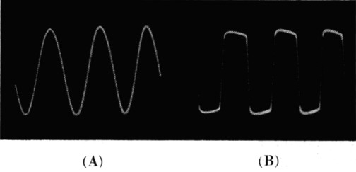
Fig. 2. A - amplifier output without clipping;
B - output with 10.4 dB of clipping.
Note that there is no change in the maximum amplitude of the wave, showing that the clipping circuit holds the modulation percentage at a given level.
Any audio-level indicating device or average-level compression will necessarily precede the clipper, since the peak level is constant following the clipper.
In designing Class B modulator stages, it must be kept in mind that the waveshape shown in Fig. 2-B represents considerably more power for the same peak value than that of the sine wave of Fig. 2-A. The ratio of r.m.s.-to-peak of Fig. 2-B is 0.9, which is considerably better than the 0.707 of the sine wave.
A practical clipper-filter circuit
The Collins 30K transmitter for amateurs employs peak clipping successfully, using the circuit of Fig. 3. The low-pass filter following the 6H6 clipper prevents high audio harmonics from modulating the carrier and causing unnecessarily wide signals. Thus a high audio level is achieved without overmodulation, and the signal is narrow.
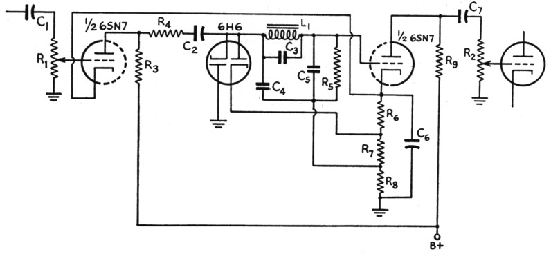
Fig. 3. A practical clipper-filter circuit using a dual triode and a 6H6.
| C1,C2,C7 | 0.01 µF paper. |
| C3 | 180 pF mica. |
| C4,C5 | 200 pF mica. |
| C6 | 20 µF 25 V electrolytic. |
| R1,R2 | 500 kΩ volume control. |
| R3,R4,R5 | 100 kΩ, ½ W |
| R6 | 330 Ω, ½ W |
| R7,R8 | 620 Ω, ½ W |
| R9 | 50 kΩ |
| L1 | 3.75 H |
The bias for the clipper is obtained from the 6SN7 cathode resistors. Clipping begins at an audio level of about three volts. The amount of clipping is determined by the voltage available at R1. Some method of checking modulation is necessary in order to adjust the gain following the 6116. R2 is set for 100-per-cent modulation with R1 advanced about half way. R2 should preferably have a screwdriver adjustment so that it will not be disturbed after it is set. R1 will then regulate the amount of clipping.
The filter cut-off frequency is 4000 c.p.s. Fig. 4 shows the amplifier response with the filter in action. The choke used must maintain its inductance over the audio-frequency range. Some chokes lose their performance at higher audio frequencies, due to capacity between turns, etc. A good textbook on filters will enable the designer to use other circuits for his particular application. The filter used in the 30K has a characteristic impedance of 0.1 megohm, which is a good practical value.
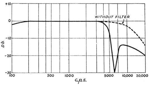
Fig. 4. Frequency-response curve of the modulation system employing the clipper-filter circuit of Fig. 3.
The cut-off frequency should be 3500 to 4000 c.p.s. Higher frequencies make for broad signals and contribute nothing to communication. If you want your rig to have broadcast quality, by all means design it to have wide frequency response - up to 20,000 c.p.s. maybe. Check it in your laboratory and be proud of it. But don't put it on the air. Use a filter. A signal that is 40 kc. wide covers up seven or eight other stations that someone wants to hear.
Filter considerations
Two common types of "pi" filters,(2),(3) are shown in Fig. 5, together with their attenuation characteristics. Fig. 5-A shows the prototype and .Fig. 5-B the composite or m-derived filter. The m-derived filter with a value of 0.6 for "m" will have a constant impedance over the voice-frequency range, and several sections can be used in tandem without mismatch. The different sections can be assigned various frequencies of high or "infinite" attenuation, and a really formidable filter will result. Terminating half-sections are utilized in a complete filter design, but for amateur use a simple filter will usually suffice. The total attenuation of the filter in decibels is, of course, the sum of the attenuations in all sections. The equation for attenuation assumes that there is no dissipation in the filter. The fact that there is a small amount of power dissipated in the filter need not bother you.
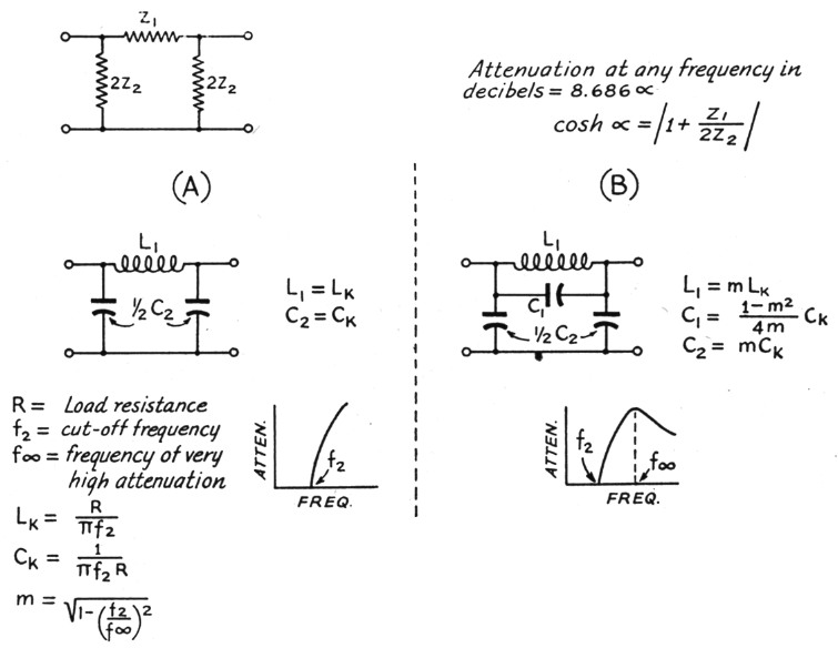
Fig. 5. Low-pass filter design. A - ,r-section; B - m-derived section.
Clipper results
Experiments were conducted at the Collins Radid Company to observe the results of using peak clipping. A listening test was very revealing, using about a dozen persons selected at random for subjects. A transmitter was used which had a clipper built into the audio system, and it was tuned to frequencies in extremely poor parts of the spectrum. The noisiest frequencies possible were selected.
The listeners were provided with headphones, and a receiver was tuned to the transmitter. As a series of nonrelated words was transmitted, they wrote down what they heard, or thought they heard. With the clipper circuit inoperative the percentage of errors was staggering. But when the clipper was used (and the over-all gain increased the same amount as was clipped) the listeners heard almost every word correctly.
The engineering model of the 30K was used to check the benefits of peak clipping on amateur bands. Results were extremely gratifying. Many transmissions that normally would have been lost in QRM and QRN were solid when the clipper was employed. Listeners reported a tremendous increase in audio with no observable broadening of the signal.
Other considerations
Since the effective microphone sensitivity is extremely high in a clipper amplifier, a noisy operating location should be avoided. Close-talking microphones and noise-cancelling microphones are helpful if the noise cannot be avoided. An alternative is to reduce the gain preceding the clipper and talk loudly.
The thought will occur that receivers can use clippers. Transmitters can utilize clipping to put more power in the sidebands and thus compete with atmospheric static or QRM. However, a receiver would be impartial; peak clipping there would benefit all signals, with special advantage for none. Experiments have confirmed this reasoning.
When a clipper is used in a transmitter, care should be taken to avoid phase shift, which occurs especially in transformers. Phase shift can tilt the clipped wave and cause overmodulation. By using an oscilloscope, phase shift can be detected. A variable-frequency audio oscillator is necessary if thorough checking is to be accomplished.
Attenuation of the low frequencies (below 150 or 200 c.p.s.) is desirable in communication equipment. A simple RC filter will be satisfactory. A rising frequency response will result, and low frequencies will not be bothersome.
Conclusions
A peak clipper followed by a filter will have the following advantages:
- Raise the audio level
- Prevent overmodulation
- Maintain a narrow signal
- Conform with FCC requirements
Thus by using this system, amateurs can have high average modulation and still conform to FCC rules and regulations. The _signal will be narrow. All these things are desirable, but many hams have disregarded the ethics of good hamming in their determination to be heard.
The clipper must be followed, by a filter if the signal is to be kept clean and narrow. (A filter should be used anyhow if maximum use of the crowded amateur bands is to be achieved.)
Because the consonant sounds are effectively amplified more than vowels, intelligibility is improved when reception is hampered by static or when frequencies are congested. The advantages of clipping rise in proportion to the interference.
This system has been proved. It is within the reach of everyone. The circuit presented can be followed with excellent results.
Acknowledgment
The clipper circuit of the Collins 30K transmitter was originally developed by P. G. Wulfs-berg for use in airborne transmitters. W. B. Bruene designed the 30K and supplied test results.
Notes
- For example, W. W. Smith, "Premodulation Speech Clipping and Filtering," QST, February, 1946.
- W. L. Everitt, Radio Communication.
- F. E. Terman, Radio Engineers' Handbook.
John W. Smith, W0UCM
N.H. Hale, W0JIH.