Narrow-band F.M. with crystal control
A reactance-modulator crystal-oscillator unit.
The system of narrow-band f.m. which forms the basis for the design of the modulator and exciter described in this article was developed before the war under the supervision of James N. Whitaker, W2BFB, and was intended for narrow-band ham phone transmission. With the advent of World War II the system was converted to narrow-deviation telegraphy and was widely used by the military services, where code transmission was carried on simultaneously over regular broadcast stations without the listeners becoming aware of the existence of the telegraphic messages.
Narrow-band f.m., we believe, is destined to become an important factor in ham radio, as it already has in commercial radio services. True, you always get some "bitter with the better," but in narrow-band f.m. there is every sign that there is going to be plenty of better and not too much bitter. It eliminates the high-power - and therefore expensive - audio equipment needed for amplitude modulation, and will reduce certain types of interference to broadcast reception - and no one will deny that the latter has been a sore spot in ham radio for a long time.
Narrow-band f.m. is just like any other type of f.m. except in the extent of the swing. How wide and how narrow are two burning questions. Also, what about noise? All these questions are going to be answered by the type of receiver we are going to use. Simply stated, all f.m. can be converted into a.m. by riding up and down the side of the selectivity curve of the receiver. Fortunately, n.f.m. (let's call it that, it's much easier), can be made to swing back and forth across either side of the selectivity curve of a communications receiver, and since most of these curves have a linear portion some 2 or 3 kc. wide there is ample bandwidth for good reception.
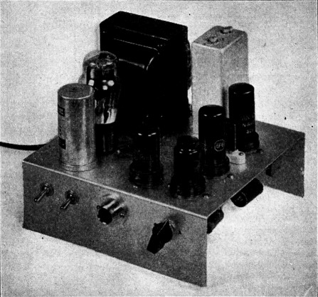
The experimental model of the crystal-controlled narrow-band f.m. unit. Controls along the front edge are the a.c. and B+ switches, microphone connector, and gain control. The power-supply section is at the left. The 6SJ7 speech-input tube is on the chassis above the microphone socket. Along the right-hand edge, from the front, are the 6C5, 6F6 modulator, and 6F6 oscillator. The oscillator tuned circuit is in the shield can at the rear.
To see how this works refer to Fig. 1, which represents a typical selectivity curve. Axis A represents the center of the curve, and starting at about 6 db. down the curve becomes straight out to about 4 kc. This means that our point of tuning for narrow-band f.m. should come at axis B. As the frequency shifts back and forth, the amplitude will vary and thus we have converted to a.m.
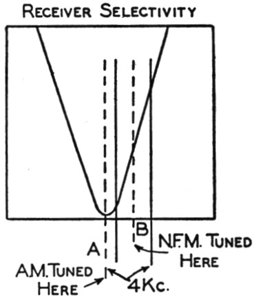
Fig. 1. F.m. reception on a communications receiver by utilizing the sloping side of the i.f. resonance curve for detection.
Considering Fig. 1, when the receiver is tuned to a signal on the high-frequency side it is true that it will also simultaneously respond to a signal on the low-frequency side. It will also respond to the same signal with the receiver tuned to either side of the resonance curve; in other words, each signal can be tuned in at two spots. The interference is doubled, therefore, even though the n.f.m. transmitter takes no more channel space than an a.m. transmitter. The situation is comparable to that in c.w. reception with a regenerative receiver or with a straight super when the b.f.o. is tuned to the center frequency of the i.f. response curve; in either case there are two tuning spots where the same beat tone can be secured. Of course, just as in c.w. reception, if there is QRM at one spot it is often possible to tune to the other side and avoid it - which does not, however, dodge the fact that it is an inherently less-selective method of reception.
Another disadvantage is that, because it is necessary to detune the receiver to get any detection at all, the a.v.c. system is working with a relatively weak carrier. Consequently, the gain of the receiver stays high and a great deal of noise rides in as compared to the case where the carrier is tuned on the nose, for a.m. reception. With conventional receivers we can knock out a lot of the noise with a correctly-designed audio limiter. The type that bites into the audio and causes distortion will reduce noise the most.
Since we have to tune to axis B, Fig. 1, to get least distortion, we can see immediately that the frequency stability of both the receiver and the transmitter is extremely important - a very little drift or detuning will ruin the quality. For this we believe that crystal-controlled oscillators are essential in n.f.m. with this type of reception.
If the foregoing seems discouraging, it is because the accent has been placed on the disadvantages of makeshift f.m. reception, rather than on the advantages of f.m. transmission. The latter seems obvious. Of course, improvement in receiver design will make all the difference in the world. Those receivers having wide-band crystal filters will do very well because the phasing notch can be moved to the unused side of the resonance curve, and thus reduce a lot of interference and noise.
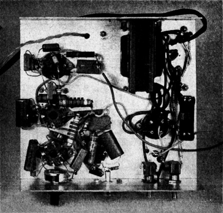
This view of the bottom shows that wiring presents no special problems. The encased unit at the top is the filter choke. The oscillator modulator is built on an aluminum chassis formed by bending an 8 × 13½ inch sheet in the form of a U with 3-inch sides. A 0-100 milliammeter is connected to the flexible leads running out of the picture to the right. The twisted pair at the top is the r.f. output link.
Crystal-controlled oscillator-modulator
In the circuit diagram of Fig. 2, the crystal frequency is varied at an audio-frequency rate by a reactance modulator; in effect, the modulator operates like a variable inductance connected across the crystal and thus varies its operating frequency at an audio-frequency rate. The extent of the frequency variation - that is, the frequency deviation - is relatively small, but is ample for narrow-band f.m. at 28 Mc. With a 3.5-Mc. AT-cut crystal the frequency can be varied over a range of approximately 400 cycles, or a total swing at 28 Mc. of 3200 cycles.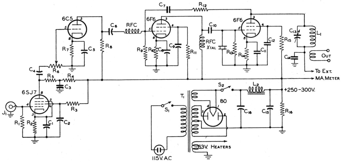
Fig. 2. Circuit diagram of the experimental narrow-band modulator unit with crystal-controlled oscillator.
| C1,C5,C8 | 5 µF 50 V electrolytic. |
| C2,C3,C4,C6,C9 | 0.01 µF paper. |
| C7 | 5.5 pF ceramic (3-30 pF trimmer adjusted to same capacitance may be used). |
| C10,C11,C12,C14 | 0.001 µF mica. |
| C13 | 50 pF variable. |
| C15 | 20 µF 450 V electrolytic. |
| C16 | 10 µF 450 V electrolytic. |
| R1 | 5 MΩ, ½ watt. |
| R2 | 1 kΩ, ½ watt. |
| R3 | 470 kΩ, ½ watt. |
| R4 | 22 kΩ, ½ watt. |
| R5 | 220 kΩ, ½ watt. |
| R6 | 1 MΩ volume control. |
| R7 | 1500 Ω, ½ watt. |
| R8 | 100 kΩ, ½ watt. |
| R9,R12 | 500 MΩ, ½ watt. |
| R10 | 390 Ω, ½ watt. |
| R11 | 100 kΩ, 1 watt. |
| R13 | 4700 Ω, 1 watt. |
| R14 | 470 Ω, ½ watt. |
| R15 | 22 kΩ, 1 watt. |
| R16 | 10 kΩ, 25 watts. |
| L1 | 56 turns No. 26 enam., 7/8 inch diam., 1_3/8 inch long. Link, 8 turns. |
| L2 | 15 H, 70 mA |
| J1 | Microphone-cable socket. |
| RFC | 2.5 mH r.f. choke. |
| S1,S2 | S.p.s.t. toggle. |
| T1 | Receiver-type power transformer; 250 to 300 volts at 70 mA |
The circuit values are rather critical and it is advised that they be strictly adhered to unless you want to do a lot of experimenting. The critical adjustment factor is really the setting of the plate tank condenser in the oscillator circuit. The curve in Fig. 3 shows that the plate current at first drops slowly as resonance is approached from the high-frequency side and then increases very rapidly just before the crystal ceases to oscillate. Best results are obtained with the tank adjusted to point A, which is just on the high-frequency side of the minimum plate-current point and on the long sloping part of the curve. With the adjustment farther along the curve on the steep side a wider swing can be obtained but operation is not as stable and on some audio peaks the crystal may be knocked out of oscillation. In any event, with the circuit values and the system shown in Fig. 2, the swing will be in excess of that required by the average receiver.
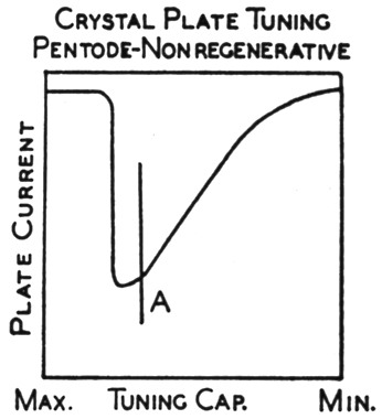
Fig. 3. Plate current vs. plate tank-condenser capacitance in a crystal oscillator. The best operating point for frequency modulation is at A, on the low-capacitance side of the minimum plate-current point.
It is desirable to build the oscillator and reactance modulator in one unit having its own power supply, as in the case of the experimental unit shown in the photographs. The n.f.m. r.f. output can be link-coupled to practically any transmitter having a 3.5-Mc. crystal oscillator. Coupling through a link wound around the present crystal-oscillator plate tank coil is suggested. The speech amplifier in the unit pictured has plenty of gain for a crystal microphone, with a 6SJ7 input stage followed by a 6C5 which in turn drives the 6F6 reactance modulator.
Aside from the normal precautions in wiring r.f. and audio circuits, no special ones need be observed in building a unit similar to this. Long leads between the reactance modulator and the crystal are not likely to be a cause of instability.
George W. Shuart, W2AMN.