An unusual rectifier circuit
Multiple voltages using two transformers and a common rectifier.
Need a bit more voltage than your present power transformer will give? Here's how to get it - along with the possibility of obtaining four different voltages from the same power-supply set-up.
The rectifier circuit to be described was originated at W1NVH and used successfully for nearly two years prior to the war. Other amateurs who have seen and used it have been so enthusiastic that it is presented here for general circulation.
The most interesting of the new circuit's many advantages and possibilities is that it offers the amateur a chance to obtain a selection of more-desirable voltages with the power-supply equipment already at hand. No longer need he be stuck with, for example, 1750 volts, when a full 2000 volts is desired. In such a case it is only necessary to add a relatively inexpensive transformer to make up the voltage deficit. The same circuit also provides for easy selection of several reduced voltages by steps, for use while tuning the transmitter and communicating over short distances.
The complete circuit is a combination of the conventional full-wave center-tap rectifier circuit and another one which at first appears unorthodox. It is shown later in Fig. 3, being first developed by stages for easier understanding.
In order to establish symbols and to facilitate explanation, the part of the circuit which is the conventional rectifier circuit is reproduced here in Fig. 1. A technical description of its operation can be found in The Radio Amateur's Handbook as well as numerous other radio texts.
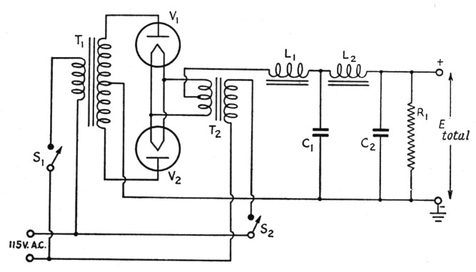
Fig. 1. The conventional center-tap rectifier circuit, with twoection choke-input filter and bleeder.
The part of the circuit which appears to be unorthodox is shown in Fig. 2. Don't worry, it works! In fact, it is frequently used in synchronous-vibrator power supplies, although infrequently employed with tube rectifiers. The symbols are the same as in Fig. 1 except that the high-voltage transformer is marked T4. T2 and T3 must be separate filament windings because the entire secondary voltage of T4 is between them.
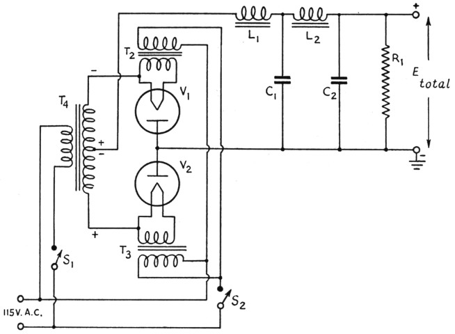
Fig. 2. "Inverted" center-tap rectifier. Except for the rectifier connections the circuit is otherwise the same as Fig. 1. Separate filament transformers, T2 and T3, are required for the two rectifier tubes.
It can be seen upon examination that this circuit is simply an inversion of the more-conventional one of Fig. 1. It can be used alone and possesses a number of advantages over the standard one, such as:
- It reduces hazards because the plate caps on such rectifier tubes as 866s and 872s can be at or near ground potential. The number of exposed high-tension leads is minimized.
- Ripple voltage in the output has always been found to be less. If T2 and T3 are not center-tapped, experimentally connect the secondary of T4 to either side of these individual windings for least ripple voltage. However, the difference in ripple is not important in ordinary use.
- There is less trouble from r.f. getting into the power supply. This is because the highpotential leads of transformer T4 are bypassed to ground for r.f. by the secondary-to-primary capacitance of the windings of T2 and T3. Also, the plates of VI and V2 are at or near ground potential.
- It permits cheaper grounded-anode cooling methods for heavy-duty rectifiers.
A brief technical analysis of the circuit is made easy simply by following the paths of the electrons through the various elements. Referring to Fig. 2, note the positive and negative signs shown at the terminals of the secondary of T4. These are given for a particular instant (or half cycle) when the upper half of T4 is operating so as to impress a negative potential upon the cathode of V1. You must then agree that the center-tap of this winding is positive at this same instant. Since electrons can flow through V1 only in one direction - that is, from filament to the plate - the supply of electrons from the negative potential readily flows across the tube to the plate, which is positive because it is connected to the positive end of the half-winding (center-tap) via the load resistor, R1. It should also be observed that the lower half of the secondary of T4 cannot function at this time because the plate of V2 is negative with respect to its cathode through the load.
The final circuit is developed by combining Figs. 1 and 2 as shown in Fig. 3. For all practical purposes we have merely added another transformer, T4, to the old rectifier (not counting extra filament windings). Because the lower-voltage transformer usually has poorer insulation, it is advantageous to place it in the T1 position where it can be kept close to ground potential.
The following statements hold true:
- The total output voltage is the sum of the voltages separately obtainable from T1 and T4 if these transformers are connected in phase to the power line. This can be experimentally determined by transposing the primary leads to the power line to obtain the greater output voltage.
- The total output voltage is the difference between the voltages separately obtainable from T1 and T4 if the transformers are connected out of phase to the power line.
- When the system is operating as in (b) there is no undue loss of efficiency because only the resultant voltage and not each of the canceling voltages is rectified.
- The polarity of the d.c. voltage delivered to the load R1 will always be the same regardless of the transformer switch connections. In other words the positive output lead will never shift position.
- The total output voltage is only the voltage obtainable from T1 alone if the primary of T4 is opened.
- The total output voltage is only the voltage obtainable from T4 alone if the primary of T1 is opened.
- The secondary of the "dead" transformer in (e) and (f) acts as an additional smoothing choke and as part of the filter circuit.
The switches shown in Fig. 3 provide the four different output voltages mentioned in (a), (b), (d), an (e) above. It goes without saying that all components must be designed for the power and insulation requirements of the circuit involved.
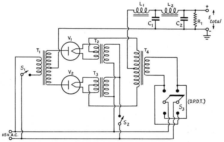
Fig. 3. The new circuit combines Figs. 2 and 3 to make four different output voltages available, depending upon whether each transformer is used alone or whether the two are used together aiding or opposing. The d.p.d.t. switch, S3, reverses the line connections to the primary of one transformer to reverse its secondary phase with respect to the other. Filter constants are the same as for conventional power supplies of the same voltage and current ratings.
Never trust this power supply any more than any of the others, since the possible potential across some of its components is equal to plus or minus death!
Commander E.E. Comstock, USCG, W1NVH.