Automatic break-in circuit
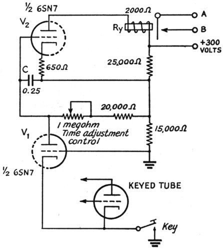
Fig. 1. An automatic break-in circuit with adjustable time delay.
With the automatic break-in circuit shown in Fig. 1 the transmitter is turned on with the first dot or dash, and is automatically turned off a predetermined interval (usually one-third to one second) after the operator stops keying. Between "on" and "off," the rig may be keyed as usual, provided that at no time is there an interval between keying characters of more than the length of time required for the automatic "off" action to take place. Thus the need for a stand-by switch is eliminated, permitting fast, efficient operation with the key as the only operating control.
The circuit has two divisions, V1, which fully charges condenser C each time the key is closed, and V2, which has an s.p.s.t. relay (contacts normally closed) for switching the whole rig on and off in its plate circuit, and a time-delay circuit in its grid return.
Under "key up" conditions, V1 is cut off, as its cathode circuit is open, and V2 is conducting, holding contacts A and B of the sensitive relay open. When the key is closed for the first time, V1 conducts, and its plate current, flowing through the potentiometer, increases the bias on V2 beyond cut-off, causing the relay to close the circuit between A and B. The condenser C, in the meantime, has charged fully, acting as a holding bias to keep V2 cut off. When the key is next opened, C starts to discharge through the potentiometer, but because the time constant of the circuit is long, it cannot discharge fast enough to permit V2 to become conductive before the next keyed character comes along to charge it up again. Thus, the circuit between A and B remains closed as long as dots and dashes are coming along at the usual keying rate. Once the key is left open long enough for C to discharge, however, the circuit opens, taking the transmitter off the air. The time delay used may be adjusted to suit the operator's individual keying speed by means of the potentiometer.
The relay may be used to close the circuits of a number of other relays, thus permitting complete station control from the key. If the delay obtained is too long or too short, try replacing the condenser C with another of the same value. Sometimes the actual capacitance may not be that shown on the label, and in one instance I found one, with the correct label and size, that gave a delay of fourteen seconds, while most condensers tried gave a two- or three-second delay at the maximum.
I suggest that the transmitter power-supply circuit be examined to insure that the automatic break-in circuit cannot turn off the same power supply that furnishes its plate voltage! If desired, a switch may be connected across the relay contacts to disable the automatic break-in circuit when you are asked to QRS when the delay circuit has been adjusted for fast keying.
Henry L. Cox jr., W8UPS/3.