Coupling 500 ohm phones to the receiver
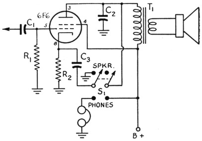
Fig. 1. Proper operation of the output stage of the receiver when 500 ohm phones are used is provided by the connection of a d.p.d.t. switch, as shown. All other parts shown in the diagram are those usually found in the receiver.
With tube-to-500-ohm-line transformers still scarce, many amateurs are faced with the problem of using 500 ohm phones with their receivers without burning out the output tube, its plate by-pass condenser, the output transformer, or all three, because of high peak voltages developed as a result of operating the tube with improper load on the voice-coil winding.
Operating the output tube as a cathode follower, as shown in Fig. 1, solves all of these problems with the additional advantage of producing excellent frequency response and very low distortion. By the addition of a double-pole double-throw toggle switch as shown, and a little rewiring of the components that are already in the receiver, proper operating conditions under both phone and speaker loads can be achieved.
| C1 | 0.01 µF 600 V paper. |
| C2 | 0.0047 µF 600 V paper. |
| C3 | 10 µF 25 V electrolytic. |
| R1 | 470 kΩ, ½ W. |
| R2 | 470 Ω, 2 watts. |
| S1 | D.p.d.t. toggle switch. |
| T1 | Tube-to-voice-coil transformer. |
Robert C. Potter, VE5TO.