The most inexpensive transmitter
A complete crystal oscillator for $3.95.
The title to this story reads like "there must be a trick to it." There is, but it rates as the neatest trick of the year, and it does offer a mighty practical transmitter for the impecunious amateur or the v.h.f. enthusiast who wants a crack at c.w. on the lower frequencies without putting out a lot of the green stuff. And if the recent rigs in QST have been too elaborate and expensive for the new ham, this transmitter goes far in the other direction.
When a letter from R.O. Deck, jr., W9JVI, asked, among other things, if we would be interested in a complete transmitter for less than five dollars, we replied, in our best cynical manner, "Sure, we'd like to see a complete transmitter for five bucks." - knowing full well that we had him and that it was impossible. He even had the effrontery to tell us that during the first week he had it on the air - at his father's shack, W9PHE - they had worked both coasts!
The reply came in due time and, for anyone who hasn't tasted crow, we don't mind saying that it can be eaten and, in this case, gladly. W9JVI's idea was one of those things that you could kick yourself around the block for not having thought of before. He built a simple crystal oscillator, with crystal but minus the tube. He then removed the audio tube from the receiver, plugged the tube in the oscillator and the power cable from the oscillator into the empty tube socket in the receiver and there he was! Simple? Of course it's simple; but so are most good ideas. The necessity for working only with headphones in the receiver is no shortcoming - most c.w. men don't use loudspeaker output anyway. And if you're not going to use the speaker output tube and the power it consumes, where is a better place to use them than in the transmitter?
The "most inexpensive transmitter" is as easy to build as it is easy on the pocketbook. By using wood for the chassis and simplified construction throughout, the transmitter can be built with very few shop tools. Using a 3.5 Mc crystal, operation in the 3.5- and 7. Me bands is possible by changing the plate and antenna coils.
Our letter of congratulations to W9JVI and a request for a story brought the transmitter itself for examination. It was tested and did all that was claimed for it, but it was built on metal, so we decided to try some simplification because many beginners might like to duplicate it and might find the metal work a bit difficult. The transmitter to be described was built in the QST lab, but we can take no credit for the basic conception - that all belongs to W9JVI. If this story helps anyone to get on the air for a minimum outlay of cold cash, send your thanks to R. O. Deck, jr., W9JVI, Roodhouse, Ill.
The transmitter can be used with any receiver that uses a 6F6 or 6V6 audio tube and has the headphone output taken off ahead of the output tube. Many receivers these days take the headphone output from the output transformer, and it is well to investigate this point before planning to use the receiver for the transmitter power supply. However, the Hallicrafter S-15, S-16, S-17 and S-18 are all satisfactory in this respect, as are the receivers described in the receiver chapter of the radio amateur's handbook. But even if you don't have one of the receivers listed above, the transmitter can be used with a 6L6 and a separate 350 volt power supply to put out a good signal. If desired, it can be used to get on the air with low power, and later an amplifier with an 807 or similar tube can be added for more punch. In any event, it won't go to waste around the shack!
The circuit
To get the most use out of the transmitter, it obviously should be capable of working on at least two bands with the same crystal. The original version of W9JVI used the grid-plate circuit, but the QST version uses the Tri-tet circuit because it gives a little better operation on the second harmonic. The circuit is shown in Fig. 1 and will be familiar to anyone who knows crystal-oscillator circuits. The cathode circuit, L1C1, is fixed-tuned to roughly 8 Mc, although provision is included for adjusting it, as will be mentioned later. The plate circuit, L2C4, is tuned to either the 3.5 or 7 Mc band, depending on which is being used. Any crystal between 3.5 and 3.9 Mc will work in the rig, but if one wants two-band operation the crystal frequency should be between 3500 and 3650 kc, since other crystals would double to outside the 7 Mc band. No provision is included for tuning the antenna output, since by judicious selection of feeder length and the size of La, the coupling coil, sufficient power can be coupled into the antenna. The antenna problem will be discussed later.
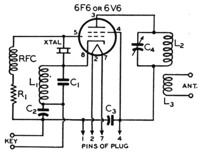
Fig. 1. Wiring diagram of the inexpensive transmitter.
| C1 | 470 pF mica. |
| C2,C3 | 0.01 µF, 600 V paper. |
| C4 | 140 pF variable (Hammarlund SM-140 or Bud MC-1876). |
| R1 | 100 kΩ, 1 W composition. |
| L1 | 5 turns No. 18 d.c.c., 1¼ inch inside diameter, close-wound. |
| L2 | 3.5 Mc: 19 turns. 7 Mc: 12 turns. |
| L3 | 13 turns and 6 turns. Requires experiment - see text. See text for L2 and L3 winding instructions. |
| RFC | 2.5 mH r.f. choke (National R-100U). |
The r.f. choke, RFC, in the grid return, is not absolutely essential but its inclusion is highly advisable because the oscillator will key better with it in the circuit. A mica condenser, C1, is used in the cathode tank circuit to tune the coil, but the other two fixed condensers, C2 and Ca, are common paper replacement types. The tuning condenser, C4, is the least expensive one that can be found, although if one had an old broadcast tuning condenser he could substitute it for the more compact one specified.
Construction
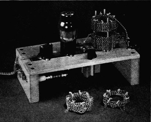
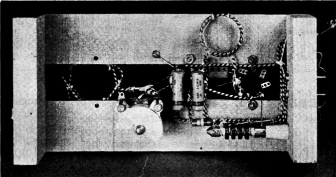
To minimize the tools required for the construction of the transmitter, a simple chassis of wood was built and finished with clear lacquer. Shellac is a suitable substitute for the lacquer, or the whole thing can be dipped in hot paraffin. Two 1¾ by 9¼ inch strips of X-inch-thick wood were fastened with screws to the two 4½ by 2¾ by flinch end pieces, leaving enough separation between the strips for the Amphenol MIP octal sockets used for the crystal and the tube. Wood screws can be used to mount the sockets, or they can be bolted to the wood strips with 6-32 machine screws. The key of the tube socket should be mounted toward the front of the transmitter, for convenience in wiring the plate circuit to the tuning condenser. The tuning condenser, unfortunately, doesn't have a long mounting shank on it, and it is necessary to drill a clearance hole for the shank and then dig away - or counterbore - clearance for the nut. The two Fahnestock clips for the antenna are secured under two of the screws used for fastening the wood strips to the right-hand end piece, and the other two clips used for the key leads are held down by machine screws on the left-hand end piece. The r.f. choke is held in place on the left-hand end piece by a machine screw. The four wires used for a power cable are brought out at the rear left under the wood strip - a half-round hole is filed in the end piece to clear the wires.
The plate coil and antenna coil are held in place on three small sticks set in the top of the chassis - penny suckers are a good source for these sticks, and one has no difficulty finding help in removing the candy from the sticks. The plate coil connects, at the bottom, to a brass machine screw soldered to a lug which is sweated to the stator terminal of the tuning condenser, and the screw is built up most of its length by adding nuts or small spacers to it. The screen end of the coil, the top end of the winding, is fastened to a brass screw that runs through the rear wood strip. The coil ends have lugs soldered to them to
A minimum of parts are used in the simple transmitter. Note the cathode coil between the tube and crystal sockets - its inductance can be changed by squeezing the coil out of round.
facilitate band-changing, but this refinement isn't absolutely necessary. The antenna-coil ends similarly fasten to two brass screws supported by short lengths of heavy wire (antenna wire, for example), and the wire is sweated to the Fahne-stock clips and to the heads of the screws.
Wiring the little oscillator isn't much of a job. As can be seen from the photographs, the wiring is done with the same wire that was used for the coils, because a single 50-foot roll of No. 18 bell wire, available in any "5 & 10" or hardware store, suffices for the whole rig with some to spare. To insure good electrical connection, the wire is soldered at every connection, which means that the wire is soldered to the heads of the brass machine screws used for the key leads and the screen end of L2 before the screws are put in place. One key lead, one end of R1, the outer foil connections on C2 and C3, and the lead to Pin 1 of the power plug are all connected to Pin 1 of the tube socket. At the crystal socket, two adjacent pins (e.g., 1 and 8) are bonded together for the grid side of the crystal and the next two pins (e.g., 2 and 3) are bonded together for the cathode side. This permits plugging the crystal into either Pins 8 and 2 or 1 and 3. The connection can be elaborated still further by bonding Pins 4 and 5 with 8 and 1 and tying 6 and 7 to 2 and 3, in which case the crystal can be plugged in any way and it will make the proper connection.
The cathode coil, consisting of 5 turns of No. 18 bell wire, is wound on a 1%-inch diameter form and then removed and tied with string at a number of places. One might think that the coil would fall apart when it is removed from the form, but the wax on the insulation of the wire helps to bond it until a few pieces of string have been tied in place. The cathode coil is mounted by its leads only but, being short, they offer adequate support.
The plate and antenna coils are wound in a simple fashion in vogue many years ago, but still practical for anyone trying to save on coil forms. :Incidentally, the coils are mighty good electrically, all showing Qs of over 300 when tested in the lab, just in case anyone wants to scoff. They are wound by equally spacing seven nails on a 2-inch diameter circle, driving the nails completely through the board used so that the heads are flush against the board. Small spikes can be used, or nails of the "8-penny" size will be satisfactory if a thin board is used. One end of the wire is secured to a nail and the wire is threaded over alternate nails, so that the coil repeats itself every two turns. When the required number of turns have been made, the end of the wire is wrapped around a nail and the coil tied together with string at the seven cross-over points. The result is an inexpensive coil having fair mechanical properties and good electrical ones, and it is difficult to build one any more cheaply. Soldering lugs are soldered to the ends of the coil for ease in changing bands, though this isn't absolutely necessary, as mentioned earlier.
The four wires coming out the side of the chassis that go to the power plug are twisted together slightly and cabled with string to form a neat cable, and the cable plug is simply the base from an old glass octal-base tube that has outlived its usefulness and which one can chisel from a serviceman or radio store. Break the tube and chew out the glass from inside the base with a pair of pliers, being careful not to break the bakelite of the base. It will help in making connection to the proper pins if a small drill, slightly larger than the diameter of the No. 18 wire, is run through the pins before the wires are inserted and soldered in place. A drill larger than No. 56 is satisfactory.
Tuning
After checking the wiring, plug in a crystal and connect the 7 Mc coil in place. Place the audio tube from the receiver in the transmitter and plug in the power cable, and connect a key to the clips on the side of the transmitter. Set the tuning condenser, C4, at about 40 per cent meshed and turn on the power to the receiver. When the tube has had time to warm up - about 30 seconds - close the key and touch a neon bulb to the plate end of L2. Or a small 10 watt electric lamp can be connected to the antenna posts with the 6-turn antenna coil in place. If C4 is set properly, the neon bulb will glow or the lamp will light. If this doesn't happen, try tuning the plate condenser until signs of output become apparent. The transmitter can then be checked on the 3.5 Mc band by putting in the proper coils - remembering, however, to turn off the receiver and hold the key closed until the power pack of the receiver had been discharged, to avoid getting a shock when touching the coil terminals. The tuning condenser setting will be about 85 per cent meshed on the lower-frequency band.
It will not be possible in most cases to check the keying on the receiver used to furnish power to the transmitter, and it is highly advisable to check the keying in a monitor or someone else's receiver. If the keying is chirpy, the cathode coil, L1, should be squeezed out of round to reduce its inductance until the keying is better. On the 3.5 Mc band, best keying will generally be obtained with slightly less capacity at C4 than the setting for maximum output. In the oscillator shown in the photographs, a slight key click on "break" was reduced almost to oblivion by connecting a 0.1 µF 600 volt paper condenser directly across the key. And don't be surprised if some crystals key better than others - such is always the case.
Antennas
It is, of course, impossible to specify an antenna that will suit everyone's location, and we can only recommend that the builder of the transmitter consult the antenna chapters of The Radio Amateur's Handbook. However, a 135 foot piece of wire for the antenna can be fed in several ways to give satisfactory results. It can be fed at one end with about 40 feet of open-wire feeders (about 32 feet of Amphenol 300-ohm Twin-Lead) or it can be fed in the center with 100 feet of open-wire feed line (about 80 feet of 300 ohm Twin-Lead). These lengths will enable one to connect the feed line directly to the antenna posts of the transmitter without the necessity for tuning condensers - other lengths may require either series or parallel condensers. Some experiment with the antenna coil may be necessary, but a small flashlight bulb in series with one of the feeders will serve as a good indication of feeder current, and will help in the tune-up process. The lamp need not be shorted during normal operation unless it burns too brightly. A neon bulb will also help in detecting r.f. energy in the transmission line, but it may not always light with this low power.
If room for only a short length of wire is available for the antenna, say 40 or 50 feet, it is best to connect its end to one antenna post and a good ground to the other. Here again some experimentation will be necessary to determine the optimum size of L3.
At some later date, the power can be increased by substituting a 6L6 for the 6V6 or 6F6 and adding a separate power supply to give 350 volts at 100 mA, but it is not advisable to increase the voltage much above this value without keeping the screen voltage down by the addition of a dropping resistor and another by-pass condenser. However, one can have plenty of contacts with the few watts obtained with a receiving-tube power supply, and several crystals are a better investment at first than the higher power. The transmitter was used by W10EG in the recent CD QSO Party, and 60 stations in 18 sections were worked, in 10 hours operating time.
Byron Goodman, W1DX.