Design of cathode-ray tube circuits
Practical procedure for building your own c.r. indicator.
The cathode-ray tube has earned a place as one of the "indispensables" in the well-equipped amateur station. This article reviews the operation of the tube in easily-understandable style and tells how to go about designing your own power supply and control circuits.
Few electron-tube types have experienced such a growth in application since the beginning of the war as the cathode-ray tube. This unique device serves as the indicator on practically all radar sets, is used in test oscillographs or "scopes" for maintenance, adjustment and trouble shooting on all types of radio gear, and also performs a valuable function as the indicator on panoramic receivers and direction finders. Its use in television receivers is, of course, by now "old stuff." With thousands of hams familiar with the value of the tube, it is considered worth while to review the principles of its operation, and to describe the circuit-design factors that need be considered in building your own gear.
There are two basic types of cathode-ray tubes in general use: the electrostatic-focus-and-deflecion type, and the magnetic-focus-and-deflection type. The latter is used under fixed conditions of operation: that is, where the deflection frequencies are well stabilized, as in television receivers here the sweep frequencies are fixed, and other r applications in military equipment. For neral purposes such as test oscillographs and panoramic receivers, use of the electrostatic-deflection type is mandatory so we shall concern ourselves with this type only.
The most important basic fact to remember about the cathode-ray tube is that it is a means of plotting a curve of some rapidly-changing phenomenon with respect to some other phenomenon. In a test oscillograph, curves are plotted of voltage amplitude as it changes with time, and in a panoramic receiver, voltage is plotted against a frequency coordinate. In the trapezoidal type of modulation monitoring, the r.f. signal amplitude is plotted against the audio or modulating signal.
How is this accomplished? Fig. 1 is a simplified tch of the electrodes or "gun structure" 'thin the glass envelope on the face end of which is coated a fluorescent salt or "screen." The spiral-wound heater, operated at 6.3-volts a.c. in most types, raises the temperature of the nickel cathode sleeve, the end of which is coated with a barium-oxide compound. The active cathode surface is roughly equivalent to the size of a pin head. Even though the total emission from this surface is only in the order of one milliampere, the quantity of material furnishing this emission is so small that caution must be used to maintain high cathode efficiency and long life. Fifteen years ago a c.r.t life of fifty hours was considered normal; today 2000 hours is not exceptional under proper operating conditions.
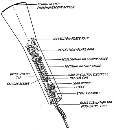
Fig. 1. Construction of a typical cathode-ray tube with electrostatic deflection.
The electrons emitted from the cathode surface are drawn toward the screen by the first anode or focusing electrode, which operates at a positive voltage with respect to the cathode. However, the passage of electrons is controlled by the grid or modulating electrode which is a cylinder surrounding the cathode with a cover plate or "aperture cup" welded to the upper end of the cylinder. The electron stream must pass through this aperture on its travel toward the first anode, and by varying the negative voltage or grid bias on this electrode the magnitude of the current can be controlled as in the case of the ordinary triode. Most c.r.t. types have a cut-off bias in the order of -40 to -50 volts under typical operating conditions, and it should be noted that a tolerance in cut-off bias of ±50 per cent should be provided. The adustment of grid bias controls the intensity or brightness of the pattern on the face of the tube, just as the grid bias controls the plate current of an amplifier tube, and at cut-off the pattern is completely extinguished. The grid should never be operated at a positive voltage with respect to the cathode since such a condition, while it may cause a greater pattern brilliance, will in a short time cause cathode deterioration and drastic loss of emission, as well as causing excessive spot size.
After passing through the grid aperture the electron stream is caused to converge and then expand again in cross-sectional area by the electrostatic field set up between the grid and the first anode. The point of maximum convergence is called the "cross-over" point, and it will assume greater significance later on in our discussion. The focusing electrode or first anode operates at a positive potential in the order of 400 volts with respect to the cathode. Variation of this voltage is the means used to focus the pattern on the screen. The first anode contains a series of apertures to form an electron lens system in conjunction with the second anode or accelerating electrode. In passing through these apertures on their way up the tube, a considerable number of the electrons in the stream are collected by the anode parts to form a first-anode current in the order of 250 microamperes. Since the stream current is controlled by the grid bias (brightness control) and since the first-anode voltage is usually derived from a potential divider and bleeder, any adjustments in the brightness level require a readjustment of the focus control to maintain sharp focus. Furthermore, the combination of the focus-voltage tolerance (usually ±20 per cent) required by the tube manufacturer and the variations in bleeder current, require adequate attention in designing the power-supply bleeder to provide sufficient focus-voltage range to operate the tube satisfactorily. This will be discussed in detail later on as we go through the design considerations of a typical power supply. Recently the tube manufacturers, in coöperation with the Army and Navy, have changed many of their gun structure designs to provide a zero first anode current, a characteristic used some time ago in the older television tubes. This simplifies bleeder design since variations in bleeder current are largely eliminated. These new tubes bear an "A" designation after the type number, such as 5CP1A.
After passing through the first-anode barrel or cylinder the electron stream is further drawn toward the second anode or accelerating electrode, which in the 5-inch tubes usually operates at a positive voltage of approximately 1500 with respect to the cathode. The electric field created by the voltage difference between the first and second anodes forms a condensing lens system for the electron stream, creating an image of the "cross-over" section of the stream on the screen of the tube, thus resulting in a sharp pin-point of light called the "spot." The second-anode potential imparts a high velocity to the electrons in the stream, providing them with a high kinetic energy which is converted into light when the electrons impinge on the fluorescent screen. The higher the accelerating potential the greater the brightness of the spot.
At this point, we now have an "electron gun" shooting a stream of electrons at the fluorescent screen to create a tiny pin-point of light. This corresponds to a motionless pencil, serving no useful purpose. Since we desire to trace a graph on the screen, some means must be provided to move the spot up and down and back and forth, corresponding to an active pencil tracing a curve. This is accomplished by means of two deflection-plate pairs, 90 degrees from each other, through which the beam passes after leaving the second anode.
Since the beam is composed of electrons, a positive charge on a surface adjacent to the beam will tend to pull the beam nearer that surface, and correspondingly, a negative charge will tend to push it away. Thus, by varying the voltage on a single plate of a pair, and connecting the other plate of the pair to the second anode, we can bend the beam toward or away from that plate; and if we connect an alternating voltage between the plate and the anode the beam will be deflected back and forth in accordance with the voltage variations. This type of deflection is called "single ended," and is a little cheaper but not as satisfactory as making both plates of a pair do some work by applying a voltage to one plate which is equal in magnitude but opposite in polarity to the voltage applied to the other plate. Thus, a push-pull amplifier feeding a deflection-plate pair will result in "balanced" deflection with a more uniform focus condition over the whole face of the tube. Examples of these two deflection methods are shown in Fig. 2. It should also be noted that by using a push-pull or balanced-deflection scheme, the instantaneous plate-voltage swing of each deflection-amplifier tube need only be half as great for the same amount of beam deflection.
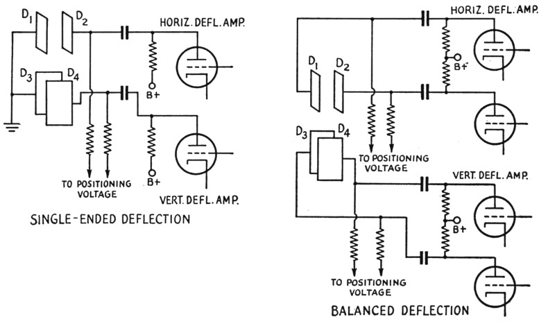
Fig. 2. Single-ended and balanced or push-pull deflection.
Since a single pair of plates causes the beam to move back and forth, the other pair, at 90 degrees to the first pair, will similarly make the beam move up and down, thus providing the two coördinates for plotting a graph. In analyzing a c.r.t. specification sheet the deflection sensitivity in millimeters per volt d.c., or the deflection factor in d.c. volts per inch deflection, is stated for a given accelerating potential. The higher the accelerating potential the "stiffer" the beam becomes, because the velocity of the electrons is greater and there-fore the time for passage of an electron through the plate structure is less, so the plates have a lesser `opportunity to exert their influence. In designing circuits, there-fore, a compromise must be made between permissible brilliance and deflection-amplifier output requirements.
The more modern tube types employ a third anode or " intensifier" formed by a conductive coating such as graphite on the inner bulb surface adjacent to the screen. Connection to this surface is made through a contact sealed in the side wall of the envelope. Intensifier-type tubes M are operated at a lower second-anode voltage so that deflection takes place while the electrons are traveling at lower velocities, and then the final high velocity is imparted by the intensifier field after deflection. While the deflection sensitivity is reduced somewhat by the intensifier voltage, the reduction is not nearly so- great as would result from the application of the same voltage to the second anode. This type of design provides the highest beam intensity with the least reduction of deflection sensitivity.
The fluorescent screen coated on the inside surface of the face end of the bulb usually produces a green trace (P1) or a white trace (P4). Other special color and light-decay or persistence characteristics are sometimes used for special purposes, but the green or the white is best suited for ham work. The screen is susceptible to burning if a bright-stationary pattern, line or spot is allowed to remain on the face for more than a few seconds. The screen is more susceptible to burning when low accelerating voltages are used, contrary to popular impression.
Power-supply design
So much for the theory of operation. Now, let's run through a typical power-supply design problem.
Problem: We wish to employ a cathode-ray tube to be used in a panoramic receiver having a 400-volt supply for the receiving-tube plates and a 6.3-volt winding for the heaters. A five-inch screen is desired to present the frequency-spectrum panorama on as large a scale as is economically practical. Good deflection sensitivity is important because we don't have large signal values, and a high-intensity display is obviously desirable.
Selection of Tube Types: A review of the available 5-inch tube types indicates the Type 5CP1 as being the most modern design. It is an Army-Navy preferred type having excellent light-output characteristics and incorporates an intensifier for maximum deflection sensitivity. Furthermore, it is produced by several manufacturers.
Power Transformer: The power transformer is usually the stumbling block of most experimenters working with cathode-ray tubes. Fortunately, there is obtainable a transformer used in commercial oscillographs which fulfills our requirements very nicely. The 5CP1 was designed to be operated at high accelerating potential. When used in the circuit shown in Fig. 3, the transformer will supply approximately 1400 volts positive to operate the intensifier and 1100 volts negative for the cathode. The second anode is connected to ground, thus providing a total accelerating potential of 2500 volts with respect to cathode. The transformer T1 indicated in Fig. 3 not only provides voltages for the cathode-ray tube, but for the other receiving-tube plates and heaters as well.
Rectifiers and Filters: Half-wave rectifiers are all that are needed for the high-voltage supply because the load current is small - less than 2 milliamperes. The 2X2 rectifies the positive cycle of the a.c. available at the 1100-volt (r.m.s.) secondary and is followed by a simple RC filter. Assuming an IR drop of 100 volts across the filter resistor R10 and across the 2X2, we can expect a d.c. potential of 1100 X 1.4 (a.c.-peak factor) -100 = 1440 volts available at the intensifier.
The 80 rectifies the negative cycle of the a.c. available at the 900 volt tap on the secondary. Assuming a 150 volt drop across the two filter sections and the 80 rectifier, a d.c. potential of 900 × 1.4 - 150 = 1110 volt is available at the "hot" end of the bleeder string.
Simple resistance-capacitance filters are used in both high-voltage circuits because they are entirely adequate, the current drain being so small, and they are considerably less expensive than the more common LC filters. The schematic indicates the component values used; they are not particularly critical. The voltage ratings of the capacitors are chosen to allow for variations in line voltage. Peak surge values of current through the rectifier sections are limited by the input resistances, R1 and R10, which are 10,000 ohms each.
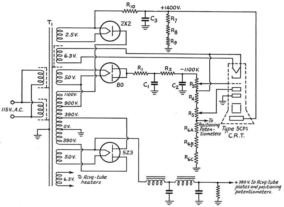
Fig. 3. Example of power-supply circuit design discussed in the text. Caution: The potentiometers associated with the cathode-ray tube electrodes operate at a dangerous potential with respect to ground!
| C1,C2 | 0.5 µF, 1500 V |
| C3 | 0.05 µF, 1600 V |
| R1,R10 | 10 kΩ, 1 W |
| R2 | 50 kΩ, 1 W |
| R3 | 75 kΩ potentiometer. |
| R4,R6A,R6b,R6C | 250 kΩ, 1 W |
| R5 | 250 kΩ potentiometer. |
| R7,R8,R9 | 5 MΩ, 1 W |
| T1 | Combined c.r.t. and receiver power-supply transformer (DuMont Type 20-64). |
It will be noted that the single tapped-secondary provides voltages for the high-voltage positive and negative supplies as well as the 400-volt system for the other receiving tubes of the equipment. Thus a single transformer is all that is needed.
The Bleeder: The bleeder, consisting of R3, R4, R5 and R6, is used to achieve good voltage regulation and thus minimize defocusing and variations of pattern size with changes in intensity or brightness-control setting. It also serves as a voltage divider to provide the proper electrode voltages for the cathode-ray tube. The design of the bleeder is all important and will be discussed in detail in the following paragraphs.
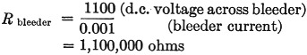
First of all, a value of bleeder current must be chosen. Currents of 1 to 3 milliamperes are usually used, so let us select 1 milliampere as being good practice. By employing Ohm's Law, we find the total value of the bleeder resistance to be
The potentiometer R3 is the intensity or brightness control used to furnish an adjustable bias to the grid of the c.r.t. The value of this potentiometer must be high enough to extinguish the beam completely and to allow for tolerances from tube to tube. The 5CP1 specification sheet indicates a maximum cut-off bias of -67.5 volts with 1500 volts on the second anode. Since the cut-off bias is directly proportional to the second-anode potential and we are using 1100 volts, a simple proportion gives:
![]()
So the intensity potentiometer should have a
![]()
The nearest standard-size potentiometer is 50,000 ohms, but since we desire some bias to spare so the intensity control doesn't have to be turned all the way to zero to turn off the beam, it is better to select a 75,000 ohm potentiometer for R3. member that this potentiometer must be nlatedd from the chassis for at least 1100 and preferably 2000 volts, for safety's sake!
The focus potentiometer, consisting of R4 and R5, is a little tricky since it must provide sufficient voltage range to focus the beam under two conditions - at nearly cut-off bias when there is no first-anode current, and at the specified brightness level when considerable first-anode current is being drawn. The first case is the easier. Since , the first anode draws no current, the idle current through the bleeder is not disturbed. The 5CP1 specification sheet indicates a first-anode focus-voltage range of 345 to 518 volts with respect to the cathode, at 1500 volts on the second anode. Consequently, in our circuit with approximately 1100 volts on the second anode, this range will be
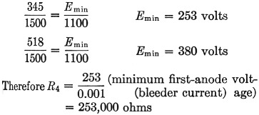
250,000 ohm is nearest standard size. This will provide a minimum potential of 250 volts for the first anode with respect to cathode. Potentiometer R5 must provide a voltage range of 380 - 250 = 130 volt.
![]()
for zero first-anode current.
The 5CP1 specification sheet indicates a maxi--mum first-anode current of 500 microamperes when the tube is operating at minimum bright-mess of 3 foot-lamberts. The effect on bleeder values caused by this first-anode current can be most easily evaluated by setting up the equivalent resistance of the first anode (when drawing current) as a shunt path across R4. The minimum value of focusing voltage is used for this condition. This equivalent circuit is shown in Fig. 4. R4 and Requiv. in parallel can be replaced by a single resistance equal to
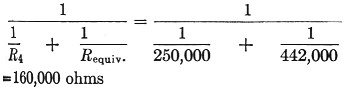
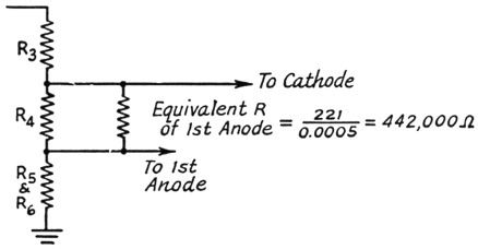
Fig. 4. Calculation of effective resistance between terminals of R4 when current is flowing to the first anode of the c.r.t.
Since our previous calculation for R4 was 253,000 ohm the difference in resistance must be furnished by R5: 253,000 - 160,000 = 93,000 ohm and our revious calculation for R5 was 130,000 ohm. So hen the first anode draws current, R5 must now 130,000 + 93,000 = 223,000 ohm. The nearest standard size is 250,000 ohms.
The value of Re may be calculated, since the voltage across it should be
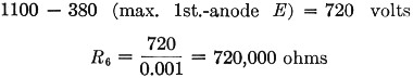
It is not recommended that more than 500 volts appear across any one resistor in the bleeder string, so R6 is broken up into three 250,000-ohm resistors, comprising a 750,000 ohm total value.
The calculations may be checked by adding up the individual calculated resistances of each unit in the string.
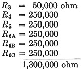
This checks pretty well with the original 1,100,000-ohm figure for the entire bleeder, much. of the 200,000-ohm difference being caused by the increase in size of R5 to handle the maximum first-anode current condition.
Deflection System: Now that the c.r.t. power supply is established, a few words about the deflection voltages are in order. Let us decide that we wish to spread the horizontal deflection over the full five-inches of the c.r.t. screen and the vertical signal deflection two inches above the horizontal baseline as illustrated in Fig. 5.

Fig. 5. Sweep conditions used in example (see text).
The c.r.t. specification sheet indicates a deflection factor of 55 d.c. volts per inch for platepair D1D2, the horizontal sweep usually being connected to this pair because, being nearer the screen, it is less sensitive than D3D4. The deflection factor for plate-pair D3D4, which provides the vertical deflection, is 48 d.c. volts per inch. These figures are for 1500 volts on the second anode and with the intensifier tied to the second anode. Since the deflection sensitivity is inversely proportional to the second-anode potential (deflection factor directly proportional) the factors for our circuit are:
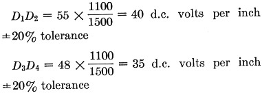
The addition of the intensifier voltage will reduce the sensitivity, or increase the factor. Applying an additional voltage to the intensifier which is equal to the second-anode voltage - in other words, doubling the total accelerating voltage - will reduce' the deflection sensitivity by approximately 20 per cent.
Since in our case the intensifier voltage with respect to the second anode is 1400 volts, the reduction due to the additional accelerating potential is approximately ![]() or about 25%.
or about 25%.
The maximum deflection signals needed then are:
D1D2 = 40 d.c. volts/inch + 25% = (40 + 25%) + 20% tolerance = 40 × 1.25 × 1.2 = 60 volt peak and
D3D4 = 35 d.c. volts/inch + 25% = (35 + 25%) + 20% tolerance = 35 × 1.25 × 1.2 = 53 volt peak.
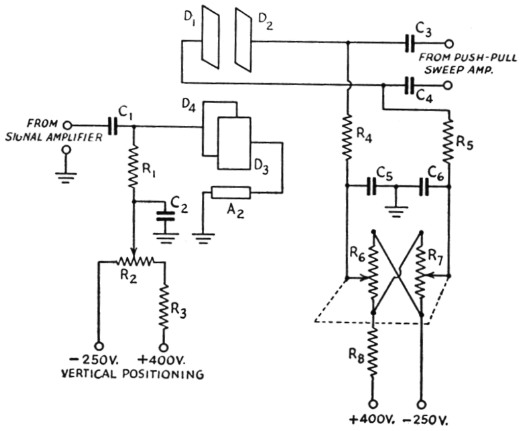
Fig. 6. Positioning circuits for single-ended and balanced deflection.
| C1,C3,C4 | 1 µF |
| C2,C5,C6 | 0.05 µF |
| R1,R3,R4,R5,R8 | 1 MΩ |
| R2 | 4 MΩ potentiometer. |
| R6,R7 | 4 MΩ dual potentiometer. |
In our particular application, the vertical deflection will only be upward from the baseline across the center of the tube, so we can achieve some simplicity and a saving in cost by using single ended deflection on the vertical axis and grounding deflection plate D3 to the second anode.
Referring to Fig. 6, the circuit formed by R1, R2 and R3 provides for the insertion of an adjustable d.c. voltage to deflection plate D4 for vertical positioning of the c.r.t. beam in the single-ended fashion, and R4, R5, Rs, R7 and R5 make similar provision in the balanced or push-pull circuit. R2 with R3, and R6 with R7 and R8, act as potential dividers. R1, R4 and R5 are coupling resistances, C2, C5 and C6 serve to by-pass any signal voltages to prevent their appearing in the power supply, and C1, C3 and C4 are d.c. blocking and coupling capacitors for the signal circuits.
Horizontal- and vertical-positioning controls are necessary because the beam usually will not fall right on the center of the screen because of manufacturing tolerances, minute leakage currents, and the effect of the earth's magnetic field.
A few precautions
Now for a few general comments on construction practice. Every effort should be made to minimize magnetic fields in the vicinity of the c.r.t. Chokes and transformers should be located as far away as possible, and should be oriented so the field that does exist has a minimum effect on the beam. Trial and error will indicate the best points of location and angles of mounting. It is best to surround the c.r.t. with a high-permeability magnetic shield, such as mu-metal. In working with mu-metal remember that after it is bent or reworked to shape, it must be annealed to restore its high permeability.
Do not scratch the glass envelope of the c.r.t. Ordinarily the bulb will withstand pressures of three or four times atmospheric pressure, and most tube manufacturers run quality tests on this and other characteristics, but a scratch will greatly weaken the bulb.
Do not allow a stationary pattern to remain on the screen except at very low brightness levels, to prevent burning of the fluorescent material.
Do not apply a positive voltage on the c.r.t. grid (with respect to the cathode). A few seconds of positive grid voltage will strip the cathode surface, which cannot be repaired.
Above all, remember you are working with high voltages. The author has found it worth while to work with one hand in his pocket as much as possible. Do not be misled by negative potential points. They are just as lethal as positive points. Do not skimp on insulation, and make your parts layouts neat, firmly anchored, and with plenty of space between high-voltage points.
The cathode-ray tube is one of the most useful indicators ever devised. The author hopes to describe in a subsequent article the constructional details of a e.r.t. indicator which can form the basic unit for a modulation monitor, panoramic indicator, high-impedance voltmeter, or, in conjunction with an amplifier and sweep circuit, as a general-purpose oscilloscope or oscillograph.
Walt Knoop, EX-W9KHG.