Standing waves - good or bad?
There seems to be a feeling in some quarters that there is something malignant about standing waves on a transmission line. By some magic, all your troubles are supposed to clear up if only you can get that "perfect" match, judging by the tales that go the rounds these days. There are, in fact, cases where elimination of standing waves may mean the difference between success and failure, but there are plenty of others where the time spent in trying to get rid of them might be used to better advantage.
It is true that line losses increase as the standing-wave ratio becomes greater. Numerically, the ratio of line loss with standing waves to the loss in the same line perfectly matched 1 is shown in Fig. 1. With a standing-wave ratio of 10, for example, the line loss is approximately 5 times as high as when the standing-wave ratio is 1. This may or may not be serious. Suppose we have a perfectly-matched line which loses 2 watts out of every 100 watts put into it. Then with a 10-to-1 mismatch, giving a standing-wave ratio of 10, the loss will increase to 10 watts. The line is still 90 per cent efficient, and there is certainly no cause for concern. On the other hand, if the loss in a perfectly-matched line is 10 watts out of 100, a 10-to-i mismatch will increase the losses to 50 watts and the efficiency will drop to 50 per cent. Here we do have something to worry about.
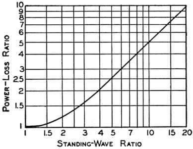
Fig. 1. The increase in line loss over the loss in a perfectly-matched line as a function of the standing-wave ratio. For higher standing-wave ratios the loss ratio is practically equal to one-half the standing-wave ratio.
This simple illustration should make it obvious that the standing-wave ratio alone is no criterion of line efficiency. It becomes of importance only when considered in conjunction with the loss in the same line if the line were perfectly matched. The loss we are talking about is the actual total loss in watts in a line of a definite length, not the loss in decibels per unit length. The latter is convenient for comparing different types of line when properly matched, but it gives no indication at all of the increase in losses with stadding-wave ratio.
To determine the effect of standing waves in a particular case, it is first necessary to find the power lost in the line when it is properly terminated. To take a concrete illustration, suppose we have 65 feet of line that has a rated loss of 1.0 dB per 100 feet at the frequency to be used. The actual loss will be 65/100 of 0.1 dB, or 0.65 dB, corresponding to a loss of 14 watts if the input is 100 watts. If the line has an impedance of, say, 150 ohms and is terminated in a resistive load of 50 ohms, the standing-wave ratio will be 3 to 1. From the curve of Fig. 1 the loss ratio is 1.65, so the actual loss will be 1.65 × 14, or 23 watts. Because of the mismatch the line efficiency has dropped from 86 per cent, the maximum possible value, to 77 per cent. In decibels, the loss is now 1.13 dB, an increase of 0.48 dB over the perfectly-matched case. In view of the fact that 1 db. represents the least detectable change in signal strength under ideal listening conditions, there cannot be much argument over the assertion that, in this particular case, a 3-to-1 mismatch is inconsequential.
The italics in the last sentence above are important. A specific illustration such as this does not warrant drawing a general conclusion that a 3-to-1 mismatch is negligible in every case. If we say that we can tolerate a loss up to 1 db. because any smaller ratio cannot be discerned by the receiving operator, then the standing-wave ratio that is permissible depends entirely on the kind of line in use, its length, and the frequency. Remember that it is the total loss in the line that counts. This loss will be greater the longer the line and the higher the frequency. A standing-wave ratio that might cause a negligible increase in loss on a short line or at low frequencies may consume most of the input power if the line is long or is operated at v.h.f. Good matching, then, becomes more important as we increase either frequency or line length.
Some representative cases are shown in Fig. 2, where the loss in db. is plotted as a function of standing-wave ratio. Curve A shows the calculated loss at 28 Mc. in 100 feet of 300-ohm Twin-Lead line which, when terminated in its characteristic impedance, has a loss of 0.84 db. The standing-wave ratio can be .almost as high as 4 to 1 before the line loss increases by one decibel, so it would be expected that the line could be terminated in any value of resistance between about 75 ohms and 1200 ohms before a listener could detect any difference in the signal strength. Such a range covers a lot of antenna systems.
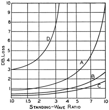
Fig. 2. Loss in decibels in a number of lines as a function of standing-wave ratio. The transmission lines and operating conditions associated with the curves are described in the text.
Curve B is for 50 feet of the same type of line at the same frequency, and when compared with Curve A shows how marked an effect the line length has on the losses. With perfect matching the loss would be 0.42 db., and the loss does not increase by one decibel until the standing-wave ratio is about 6 to 1. With the shorter line, therefore, the terminating resistance can lie anywhere between 50 ohms and 1800 ohms; only outside this range will there be a noticeable change in the signal strength as compared to a 300-ohm load. At the 4-to-1 ratio tolerable in the case of the 100-foot line, the loss in the 50-foot line is only 0.52 db. greater than it is with perfect matching.
The effect of frequency is indicated by Curve which is for 100 feet of 300-ohm Twin-Lead operating at a frequency of 7 megacycles. The rated loss of 0.3 dB with perfect matching increases to 1.3 dB at a standing-wave ratio of 7.5 to 1, so the line can be terminated in any resistance between 40 ohms and 2250 ohms without noticeable loss in signal strength. Curve C, incidentally, is practically identical with a curve for 100 feet of open-wire line operating at 28 Mc., assuming a loss of 0.1 dB per wavelength for the open-wire line.(2) Comparison with Curve A gives some idea of the improvement to be anticipated when air-insulated line is substituted for a line with solid dielectric. Losses in solid coaxial cable such as RG-11/U are practically the same as in 300-ohm Twin-Lead.
All of the above discussion has been on the basis of the increase in line loss caused by a mismatch. Perhaps a more sensible way to look at the question is to assume that the total line loss should not exceed one decibel; in other words, to limit the line loss to a figure such that it cannot cause a perceptible decrease in the strength of the signal. To meet such a specification the standing-wave ratio in the case of the 100-foot line of Curve A should not exceed 1.6 to 1, and for the air-insulated line of Curve C should not exceed 6 to 1. The 50-foot line of Curve B could tolerate a standing-wave ratio of 4 to 1. It is worth noting that it will be impossible to keep the line loss below 1 db., even with perfect matching, if the line exceeds a certain length; in the case of the 300-ohm line this length would be 120 feet at 28 Mc. The only remedy is to arrange things so the line can be shorter or to use a line having lower inherent losses. The polyethelene dielectric material developed during the war is excellent stuff, but it is not perfect. At v.h.f. it is quite possible to lose nearly as much in a long line, even with good matching, as is gained in a beam antenna. Readers may remember some remarks of Ed Tilton's on the subject of height versus line losses a few months ago.(3)
Curve D is of considerable interest because it illustrates a practical point of some importance and also represents a situation in which the curve of Fig. 1 falls down. Curve D is calculated on the basis of Fig. 1 and a 100-foot 300-ohm Twin-Lead line operating at 144 Mc., where the rated line loss is about 3 db. Using the method of calculation previously outlined, the total input to the line is dissipated in the line itself when the standing-wave ratio is a little less than 4 to 1. No higher standing-wave ratio than this could exist, even if the end of the line were short-circuited or left open. Actually, things don't happen in quite that way. The loss ratio in Fig. 1 is calculated on the assumption that the standing-wave ratio is the same everywhere along the line, but the fact of the matter is that in a line such as is represented by Curve D the standing-wave ratio varies along the line, being greatest at the far end and least at the input end. Although Curve D is therefore not to be taken too literally, it does have two lessons to offer: There is a definite limit to the standing-wave ratio that can exist at any given point along a line in which the losses are high; and any checking of standing-wave ratio on such a line should be done as close as possible to the antenna if the check is to mean anything. It emphasizes again, too, the importance of keeping a v.h.f. line short if the plus decibels in the beam are not to be swamped by the minus decibels in the line.
Below 30 Mc. and with lines of reasonable length it hardly seems necessary to worry much about getting that "perfect" match if a little forethought is exercised. Take the case of the popular 3-element close-spaced array, for instance. Guesses as to the impedance at the center of the driven element seem to range anywhere from 8 ohms to about 12 ohms; possibly there is that much actual variation with different tuning adjustments. A good way to match any two different impedances is the quarter-wave transformer or "Q" section shown in Fig. 3, if it is physically possible to use it. Since the terminating impedance is low, a low-impedance transformer is needed. Line material having an impedance of the order of 70 ohms is available - one, for example, being 75-ohm transmitting-type Twin-Lead.
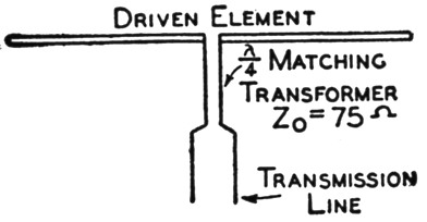
Fig. 3. Quarter-wave matching transformer between the driven element of a parasitic array and a parallel wire transmission line.
A quarter wavelength of this line at 28 Mc. will be a little over 6 feet long. Terminated in 8 ohms, the standing-wave ratio on the transformer will be 9.4 to 1, and in 12 ohms it will be 6.25 to 1. On the basis of the rated loss, matched, of 1.4 dB per 100 feet, the loss in the transformer will be 0.43 db. for the 9.4 ratio and 0.3 db. for the 6.25 ratio. In the first case the transformer output impedance will be 705 ohms and in the second case 470 ohms. The main feeder evidently should be a 600-ohm line in this case. If the antenna impedance is 8 ohms, the transformer will give a rather close match with a 600-ohm line; the standing-wave ratio will be less than 1.2 and the losses will be negligible as compared with an ideal match. If the antenna impedance is 12 ohms the standing-wave ratio on the line will be less than 1.3 - approximately the same as with an 8-ohm load. With any intermediate load value the standing-wave ratio will be still smaller.
However, the use of 300 ohm line is not out of the question with the same transformer. With a 300 ohm line the standing-wave ratio will be under 2.5 to 1 if the antenna impedance is as low as 8 ohms, and will be under 1.6 with the 12 ohm load. Even on the 100 foot line (Curve A) the increase in loss as compared to a perfect match is only about 0.35 dB, with the worst mismatch. Adding the transformer loss of 0.43 dB gives a total increase of 0.78 dB as compared to a perfect match with the same line and a loss-free matching system. Since the loss in the latter case is 0.84 dB, the total loss between the transmitter and antenna is 1.6 dB. This is not an ideal situation, it is true, but most of the loss is there already if this particular type of line is used; the difference between this system - which requires no adjustment beyond cutting the transformer to the proper length - and the arduous business of trying to eliminate standing waves completely does not add up to a detectable improvement in signal strength.
Some other things - which will have to be left for later discussion - come into the picture, but in general it seems quite obvious that standing waves are not necessarily disastrous, especially on frequencies below the v.h.f. region. Unless the line is overly long it is possible to dispense with tedious adjustment of matching sections - work that often results in no better actual performance because of the real difficulty of making reliable measurements on transmission lines.
Notes
- From Meagher & Markley, Practical analysis of ultrahigh-frequency yransmission lines, published by RCA Service Company, Inc., Camden, N. J.
The equation of the curve is where R is the standing-wave ratio.
 - The theoretical loss is about 0.1 dB per hundred feet at this frequency in a line constructed of No. 12 wire, but actual losses run somewhat higher. If the line is well balanced, the figure used above should be conservative.
- Tilton, "Need there be line of sight?" QST, March, 1946.