A Tuned-line matching transformer
Simplified matching for close-spaced beams.
Here is a straightforward method of matching an open-wire line to a close-spaced beam, or other low impedance, which occupies considerably less space than the usual quarter-wavelength matching section. Complete information on the adjustment procedure is included, as well as how to go about the initial calculations for approximating the constants.
Matching an untuned transmission line to an antenna is always a problem for the radio amateur. Various schemes have been proposed, all having desirable and undesirable features. The matching stub is unwieldy if the antenna is to be rotated. The condenser-coil scheme suggested by the author(1) permits rotation but the coil must be protected from the weather and the adjustments of the coil may be difficult. Since tuned parallel conductors act like parallel resonant circuits, it is possible to use them as an impedance transformer. The physical length then becomes less than the usual quarter wavelength. For a three-element close-spaced beam at 28 Mc., when matched to a 575-ohm untuned line, a quarter-wavelength stub of 8 feet is shortened to about 14 to 28 inches when using a tuned line for matching, and definitely has some interesting possibilities.
For a beam antenna of low radiation resistance, the matching transformer should be of low-loss construction, since the circulating currents are high. The maximum voltage developed on the tuned line appears at the condenser, and is equal to that on the untuned line, so the insulation may be the same for both. Tubing the same as used for the antenna elements is satisfactory for the tuned line, since it is rigid enough to maintain its spacing.
To adjust such a system, a simple trial-anderror procedure as outlined by the author(2) can be employed. For those interested in a specific application, the description and operation of a tuned line as an impedance-matching transformer will first be described. To those that have other or similar requirements and wish to design their own, mathematical equations will also be presented. The system can be adjusted without recourse to a separately-excited antenna if some means is provided to indicate standing waves on the transmission line. A simple indicator is a pilot bulb shunted across a few inches of feeder and antenna. Place one on the transmission line at the junction with the transformer, another 1/8 wavelength from the junction, and a third ¼ wavelength from the junction or 1/8 wavelength from the second bulb. Another bulb on the radiator at the junction with the transformer will indicate antenna current. Fig. 1 shows the necessary setup. Set the length of the antenna elements at the usual values and connect the untuned line and tuning condenser to the tuned line. For 29 Mc., make the length of the tuned line about 28 inches to start. Set the transmitter tuning condenser at the capacity for resonance, couple the untuned line to the rig and turn on the power. Vary the tuning condenser until maximum antenna current is indicated. Vary the coupling to keep the power input at reasonable values. If the length of the antenna and tuned line are correct for the frequency, no standing waves will appear on the untuned feeders - otherwise adjustments are in order. First adjust the length of the radiator element to resonance and lastly the length of the tuned line to eliminate standing waves. From the shape of the standing waves, the condition of antenna resonance can be established as outlined by the author,(1) as in Fig. 2. It is not necessary to shift frequency to determine the frequency of maximum loading.
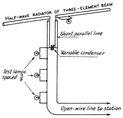
Fig. 1. A simplified matching system for feeding close-spaced arrays with open-wire lines, using parallel tubing for the inductance elements. The tune-up procedure is simplified by tapping three small lamps on the line as shown.
The beam in use at W2JO uses a director element 15 feet long, a radiator 7 feet 10 inches each side of center and a reflector 16 feet 11 inches long, all of 1-inch diameter tubing. The spacing between elements is 41 inches. The parallel line, of 1-inch diameter tubing spaced 6 inches, is 28 inches long. The open-wire line is No. 14 spaced 4 inches - nominal impedance, 575 ohms - and the test lamps are spaced 48 inches along the line.
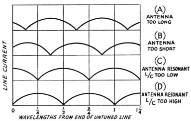
Fig. 2. The variation in line current along the open line for nonresonant antenna and incorrect L/C ratio in the matching transformer.
A nonresonant antenna will present a reactive load to the transmission line and cause standing waves. An antenna that is too long for an operating frequency will act like an inductance and resistance in series and the transformer will present a similar type of load to the transmission line. The standing waves will look like that of Fig. 2-A. A minimum current point will occur somewhere within X wavelength of the end of the transmission line. Similarly, an antenna that is short will act like a capacitive load to the un-tuned line and standing waves will look like Fig. 2-B. No adjustment of the L/C ratio of the transformer can produce a flat line if the antenna is nonresonant. When the antenna is resonant, a flat line is possible if the L/C ratio is correct. Otherwise, standing waves will occur with maximum and minimum currents at one-quarter wavelengths from the end, depending upon the L/C ratio. If the L/C ratio is low, the standing waves will look like Fig. 2-C. If the L/C ratio is high, the standing waves will look like Fig. 2-D. Lengthen the tuned line by moving the tuning condenser and untuned line connection away from the antenna for the case of Fig. 2-C. Shorten the tuned line by moving them toward the antenna for the case of Fig. 2-D. Allow extra length for the tuned lines to permit such an adjustment. The excess stub can be removed after the correct length has been found, although it appears to have negligible effect on matching, provided it is not excessive.
The tuned lines do not have to be in a straight line. They may be curved but not folded. Neither do they have to be parallel but may converge or diverge. The only requirement is that the necessary inductance be provided. The system has performed for the author and the photograph shows how it is assembled. The tuning condenser must be waterproofed, but the insulation need not be any better than for typical untuned lines. The tuned lines can be exposed to the weather which is an advantage over the coil scheme. The device has the decided advantage that it allows adjustments for matching the antenna and transmission line. This is impossible with quarter-wavelength matching transformers where the spacing and length are fixed. It permits matching of low-impedance beam antennas to untuned lines with reasonable line spacings. For example, a 28-Mc. three-element antenna of 8-ohm impedance, if matched to a 600-ohm line, would require a quarter-wavelength matching transformer of
![]()
About 5 feet of 70-ohm coaxial line would be required, but there is no provision for adjustments since its impedance and length are fixed. Parallel elements would have to be 8 feet long, large diameter and abnormally close-spaced.
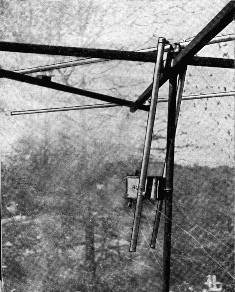
The variable condenser used in the matching system is housed in a weatherproof box clamped to the mast that supports the beam. The weatherproof box also serves as a support for one end of the short tubing used as the inductance elements in this method of matching. By loosening the clamp supporting the box and the two clamps that make connection to the tubings, the effective length of the inductance elements can be varied. The condenser is adjustable from the ground, through strings and a crossarm on the condenser shaft.
It is desirable to have the condenser variable. A suitable control to operate it while in position can be developed by the individual. The condenser should preferably be a double stator with the rotor floating, to eliminate contact losses.
To design an impedance-matching transformer for any other conditions, the equations to use are presented again here:
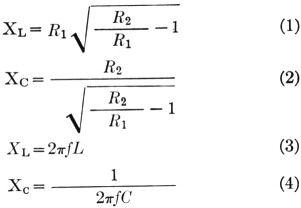
The length of the tuned line is obtained from the formula
![]()
where:
R1 = antenna impedance in ohms
R2 = untuned line impedance in ohms
XL = inductive reactance of tuned line in ohms
Xc = capacitive reactance of condenser in ohms
L = inductance of tuned line in henries
C = capacitance of condenser in farads
f frequency in cycles per second
l = length of tuned line in any units
X = wavelength in same units as l
Zt = impedance of tuned line in ohms
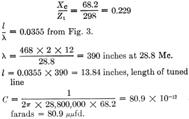
Equation 5 is plotted in Fig. 3 and is more convenient than the equation to solve for the length of the tuned line, as it eliminates the use of trigonometric tables. The values obtained from these equations are approximate and serve as a start for further adjustments. The capacity of the condenser is obtained from Equations 2 and 4 and the length of the tuned line from Fig. 3.
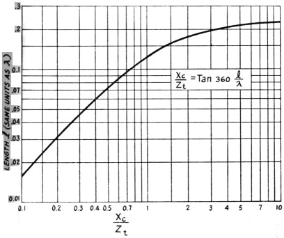
Fig. 3. A plot of Equation 5, showing the length of the tuned line for various values of XC / Zt
The design calculations for the author's antenna follow:
R1 = 8 ohms, assumed antenna impedance of three-element beam
R2 = 575 ohms, impedance of open line of No. 14 wire spaced 4 inches
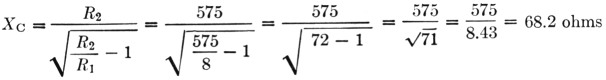
Zt = 298 ohms, impedance of open line of 1-inch diameter tubing spaced 6 inches
The formulas apply for all cases where the line impedance is greater than the antenna (load) impedance. Where they are equal, the capacity C will be zero and the length l = 0.25 wavelength. In other words, an untuned quarter-wave matching section will result and could be omitted with the same results.
Notes
- Gadwa, "An impedance-matching transformer," QST, Feb., 1943.
- Gadwa, "Standing waves on transmission lines," QST, Dec., 1942.
- Many factors difficult of prediction enter into the resultant impedance of the driven element in a close-spaced array. The tuning of the parasitic elements, the height above ground and, at high frequencies, the ratio of element length-to-diameter all influence the antenna impedance. For these reasons, close-spaced arrays should be adjusted in position for best results. The big advantage of Dr. Gadwa's matching system is that the antenna can be tuned near the ground, if necessary, and the matching can be done conveniently after the array is in place, since it is only necessary to be able to reach the tuning condenser box and where it is tapped across the line. This does not imply that tuning the antenna near the ground will give the optimum adjustment - it probably won't - but at least it will be approximate, and the feeder-line match will be exact. - Ed.
1 µµF ≡ 1 pF
Dr. T. A. Gadwa, W2JO, EX-W2KHM.