Clean-cut break-in keying
Primary keying and a T9 note.
Much break-in keying is chirpy and full of clicks, and much primary keying isn't T9 and won't handle bug sending. Here is a keying system which retains the acknowledged advantages of good primary keying and break-in operation with none of the disadvantages. Since primary keying is recognized as the "keying least likely to cause BCI," this article merits the attention of every c.w. man.
Ten years ago, if someone had said that he could key his whole transmitter in the primary and produce sharp break-in keying with a T9 note, we probably would have said that it just could not be done. Believe it or not, it can be done. Here is the story of such a system of primary keying.
From 1932 until 1937, W1LZ was keyed conventionally in the primary of the final power supply (Fig. 1). The power-supply filter nicely eliminated all clicks but, because of the keying lag, the filter was of necessity only a small input choke and a 1-pfd. condenser. In 1937, the FCC began to bear down hard on near-d.c. notes, and we were politely informed that our signal would comply with the law only if the power supply were more adequately filtered. Necessity then became the mother of invention; a long series of experiments was begun which led finally to the primary-keying system to be described.
Keying only in the primary of the driver power supply was first tried. The keying characteristic was none too good, and the note still could not be made really pure without introducing a bad keying lag. Keying in the primaries of both the driver and final power supplies proved to be no better. A resonant filter on the final supply gave better keying, but resulted in pronounced tone modulation, in addition to ruining the mercury-vapor rectifier tubes.
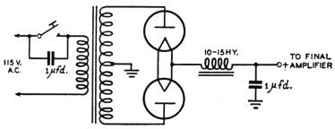
Fig. 1. Primary keying first used at W1LZ. It is impossible to obtain crisp keying and a T9 signal when only the final-amplifier supply is keyed.
T9 primary keying
Then a faint glimmer of inspiration began to flicker. If there were only some way to keep the filter condensers of the final power supply charged all the time the transmitter was in operation, there would be no bad lag as the filter charged and discharged with primary keying. Automatic grid-leak bias was being used on the final amplifier, but a bias pack with higher than cut-off potential was connected across this grid leak. Things began to happen fast. We had stumbled on the secret of clean primary keying with a pure d.c. note!
First, by keying simultaneously the respective primaries of the driver and final power supplies - second, by using the fixed more-than-cut-off bias on the final amplifier - and third, by not connecting a bleeder across the final power supply, when the key was lifted, excitation was immediately removed from the final amplifier, the fixed-bias pack sharply cut off the plate current of the final, and the final filter condensers remained charged. True, the first time the key was pressed the transmitter acted as it would under normal primary keying; the filter condensers and chokes storing up energy drew heavy current from the line. But from that time on, the output voltage of the filter remained practically constant, because there was no drain from the supply with the key up.
When the fixed-bias pack was used and the final power supply only was keyed, the continuing excitation from the driver prevented cut-off of the final amplifier's plate current and permitted the final amplifier to drain the filter of the final power supply as soon as the key was raised, thus producing a keying lag. If the fixed-bias pack was eliminated, but the driver and final power supplies were keyed simultaneously, plate current of the final amplifier did not cut off when the key was opened, and consequently the final filter discharged through the tube and caused a keying lag. Of course, connecting a high-current bleeder across the final power pack would also drain the final filter when the key was raised. With no final bleeder, however, and with simultaneous removal of excitation and application of cut-off bias to the final amplifier, we had what we had been seeking - lagless primary keying.
| C1,C2,C3,C4 | 2 µF |
| C5,C8 | 1 µF |
| C6,C7 | 4 µF |
| C9 | 0.1 µF |
| R1 | 17,000 ohms. |
| R2 | 20,000 ohms. |
| R3 | 10 megohms. See text. |
| R4 | 10,000 ohms. |
| R5 | 30,000 ohms. |
| L1,L2 | 15 H |
| L3 | 5 H |
| L4,L5 | 8 H |
| Ry | Keying relay. See text. |
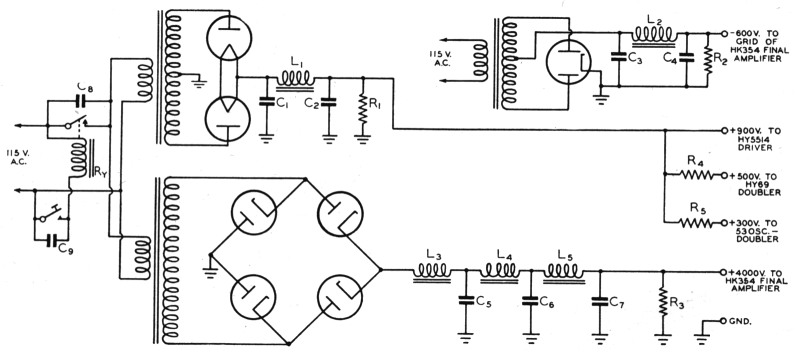
Fig. 2. The break-in primary keying used at W1LZ which gives lag-free T9 keying. The large amount of filter in the final-amplifier supply is not necessary - it was included only to prove that any amount can be used without introducing lag.
The clean-cut "make" and "break" of the keying thrilled us. Now to try some real filter in the final power pack. We piled the chokes and condensers on until the note was unquestionably T9. We were keying in the primary with no lag and with a truly p.d.c. note!
This new system was so effective that several local amateurs were persuaded to experiment with it. They had no difficulty in obtaining the same results. Radio published two articles we wrote on the system in their March and April, 1937, issues. Incidentally, remember that old saying about great minds running in the same channel? W6CUH described a similar system in an article appearing simultaneously in the March, 1937, issue of QST. Hi!
Break-in operation
When W1LZ was put back on the air after the war, this plate-current cut-off form of primary keying was again used. The ability to work break-in had always seemed desirable. Perhaps it could be used with primary keying, by applying the plate cut-off principle already discussed. Well, there's nothing like trying.
Our present 14-Mc. rig consists of a Type 53 twin-triode crystal oscillator/doubler, an HY-69 beam-pentode doubler, an HY-5514 triode driver, and an 11K-354 triode final. It was decided to use the 900-volt pack which fed the HY-5514 alone to power also the 53 and HY-69. A suitable dropping resistor was connected between the positive terminal of the 900-volt pack and the plates of the 53; and another resistor, with less voltage drop, between the positive terminal and the plate of the HY-69. (Power wasted in these dropping resistors is negligible, because the plate current for the 53 is only 20 ma. and plate-andscreen current for the HY-69 only 40 ma.) Simultaneous primary .keying of the 900-volt and the final plate supplies now keyed all stages of the transmitter (Fig. 2). Darned if it didn't work! When the key was pressed, we had clean-cut primary keying of a T9 note, and complete break-in.
Considerable tinkering disclosed that the best filter for the 900-volt oscillator/doubler/driver pack is a condenser-input set-up consisting of 2 µfd., 15 henries, and 2 µfd. Choke input is not recommended, because it will introduce an undesirable lag. If two 866A tubes are used for rectifiers in this supply, the peak current will be below the maximum permissible value (250 ma.), even with condenser input. If you prefer high-vacuum rectifier tubes with condenser input, the 1616, 5R4GY, 5Z3, or 80 (dependent on voltage and current) would be suitable. A 45-volt B battery in addition to resistor bias is employed on the HY-69 and HY-5514 stages, and combination cathode and resistor bias on the 53 stage - for protection only.
By experimentally keying the 53 oscillator/ doubler stage alone, it was found that a 17,000-ohm bleeder across the 900-volt pack quickly drains energy from its filter when the key is opened, and thus removes traces of keying lag or chirp. Since a bleeder is required across this supply, you may prefer to use it also as a voltage divider, and thereby eliminate the dropping resistors. Or you may need no dropping resistors, because your oscillator, doubler, and driver stages may all operate at the same potential. We prefferd separate dropping resistors for flexibility adjusting our various voltages and the bleeder current. No special treatment of the crystal stage is necessary, except that it must be one that is reasonably free from chirps.
Yes, the keying will follow a bug easily at high speeds. The keying relay used is a d.p.s.t. 115-volt a.c. Model 1177-BF Leach relay with the two poles connected in parallel and the ¼-inch contacts adjusted to close simultaneously. To reduce sparking, a 0.1 µF condenser is connected across the key contacts and a 1 µF condenser across the relay contacts. If you can find a suitable relay with a 12-volt a.c. solenoid, sparking at the key contacts and shock hazard will be lessened. Adjustment of the dot lever of the bug is made until the plate current of the final amplifier hovers around 50 per cent of the normal value when the dot lever is held over.
This system of keying does not even sound like primary keying. Most amateurs guess it to be blocked-grid or tube keying. Needless to say, there is not a click to be heard by local hams or by BCLs, even with a kilowatt input to the final amplifier. You can make the tone as pure as you wish simply by adding filter to the final power supply.(1) At 4000 volts, we have 5 henries, 1 µF, 18 henries, 4 µF., 18 henries and 4 µF - which at that potential is certainly an adequate filter. Actually this large filter is not necessary, and was employed only to prove that it is feasible to use a husky filter. The filter has been increased successfully to as much as 17 µF at 4000 volts.
There are some additional ideas in which you will be interested, if you decide to test this system. For safety's sake, you may wish to have a high-resistance bleeder across the output of the final power supply. A one-watt one-megohm resistor for each 400 volts of power-supply potential will be satisfactory. In practice, however, you may omit this bleeder, if your bias pack is switched on and off simultaneously with your plate supplies. When the bias pack is switched off, the energy in the filter condensers is dissipated instantaneously through the static d.c. plate resistance of the final-amplifier tube.(2)
If your final amplifier is running well into the Class C region under saturated grid conditions, the filter for the oscillator/doubler/driver power pack need not be large. A small percentage of a.c. ripple in the grid excitation will not introduce serious hum into the output of the final amplifier, because under such Class C conditions, your final amplifier is insensitive to grid-bias modulation. Remember, however, that too little filter on this pack gives very sharp keying, but tends to modulate the note undesirably. Let your monitor be your guide.
No input choke should be included in the final grid-bias pack. Filter condensers for this pack should be capable of withstanding the full operating grid voltage, but their capacitance may be small, because current flows in this pack only when the key is up. With the key down, current flows through the grid leak in the reverse direction, and no current is supplied from the pack.(3)
Since the potential across the final power-supply filter remains constant (filter is always fully charged) and at the normal key-down- operating value, you can readily understand why clicks and thumps are washed out better than they would be with other forms df keying. This is particularly true if the voltage regulation of the final power supply is not well-nigh perfect with other keying methods. Then, too, with this system, the power-supply filters themselves serve as excellent key-click filters.
In a nutshell, this simple plate cut-off primary keying system requires only that you: (1) key the final power supply and the combined oscillator/doubler/driver supply simultaneously in the primary, (2) connect a simple bias pack with more than cut-off potential across the grid-leak resistor of the final amplifier, (3) use no high-current bleeder for the final power supply, but (4) use a bleeder across the oscillator/doubler/ driver pack which should have condenser input and an adequate but not excessively-large filter. The final power supply may have as much filter as you desire. Output voltage of the final grid-bias pack should be approximately twice the cut-off potential (for a triode, cut-off potential is the plate voltage divided by the amplification factor).
Principal advantage of the break-in system of plate cut-off primary keying described is that it is sure-fire. There is no exasperating cut-and-try of chokes, condensers and resistors for a special keying filter. Other advantages are: no clicks on broadcast or amateur bands; clean-cut fast break-in keying; a T9 note; no backwave; only two plate supplies required; absence of troubles with hash from the mercury-vapor rectifier tubes; no peak-voltage strains on the insulating materials of filter condensers and chokes; no need for a wasteful high-current bleeder on the final power supply.
Although VFO has not been tried with this keying system, it should be satisfactory if your VFO keys well with combined plate-and-screen keying. We do know that it gives crisp, chirpless keying with X-, Y- or AT-cut crystals in holders with fixed or variable gaps.
Did we hear someone say, "It sounds FB, but what about blinking the house lights?"? Yes, primary keying or any other method of keying a kilowatt rig will blink the lights, if an ordinary electric-light line is the a.c. source. If you run a kilowatt, however, you should have a special, heavy 230-volt three-wire a.c. line, to reduce blinking and to keep your tube filaments within plus or minus 5 per cent of their rated voltages. With a heavy line suitable for operating an electric stove, you will not be troubled by blinking lights. And with this keying system, you will have keying which sounds as sweet as it is simple.
Notes
- This is true provided certain conditions are maintained. It is imperative that the output stage be adequately excited, so that it will be operating Class C at all times and hence not amplify any amplitude modulation from the driver stage. Further, no frequency modulation can be introduced at the oscillator stage, but this condition is met by an oscillator which doesn't chirp with keying. - Ed.
- Do not be alarmed by the high surge current and plate dissipation which occur during this momentary discharge cycle. Actual time of the several time constants required by the R-C combination of d.c. plate resistance and filter condenser to bring the filter potential by degrees to zero is measured in a few milliseconds. As was learned from radar applications, under such brief pulsing conditions a tube will withstand many times the peak load it would in continuous duty. At W1LZ, the plate milliammeter flips up to lees than normal current during this brief surge and causes no damage to the meter, but it is well to check the meter when first trying the system.
- Another type of bias supply that is useful in auch applications is one making use of VR tubes. See Fig. 810, The Radio Amateur's Handbook, 1947 edition. Also, McCullough, "Another approach to high power," QST, February, 1940. -Rd.
Harry G. Burnett, W1LZ.