N.F.M. Reception
From the beginning of its commercialization, frequency modulation has been promoted as a noise-reducing system, permitting higher fidelity in broadcasting and a better signal-to-noise ratio in emergency services operating with mobile equipment. The latter point is of considerable interest to us amateurs; anything that will enable us to hear weaker signals through the noise level is all to the good. Practical information on how to build and adjust amateur f.m. equipment and the kind of results it will produce has appeared in QST from time to time over a period of several years. Nevertheless, except for a few more or less isolated experimenters, amateurs have made practically no use of f.m. for the purpose of obtaining a better signal-to-noise ratio in reception.
The over-all situation - a rather curious one - is this: F.m. receivers are used to some extent on v.h.f., particularly 144 Mc., as a means for obtaining better-sounding speech from modulated oscillators than can be secured with straight a.m. reception; and f.m. transmitters are used to some extent on the 28-Mc. band as a means for operating 'phone without causing interference to broadcast reception. So in the one case we have a group of receivers without any transmitters and in the other a group of transmitters without f.m. receivers. And in neither case is f.m. used because of its outstanding feature, noise reduction, but because some peculiarity of the system happens to meet an amateur need better than a.m. methods.
We wonder whether this doesn't indicate that the amateur perspective on f.m. shouldn't have a different orientation than the commercial. Our problems are different, certainly. Below 30 Mc. our principal problem is QRM, not noise. In fact, a.m. noise-reducing systems have been developed to the point where man-made noise can be eliminated practically as well in a.m. reception as it can by an f.m. receiver, when the channel utilized is kept down to the width of an a.m. transmission. And on frequencies below 30 Mc. wide-band f.m. is out of the question.
So far, reception of narrow-band f.m. on the 28-Mc. band has been by the rather makeshift method of detuning the incoming signal so that it falls on one side of the selectivity curve and its frequency modulation is thereby converted to amplitude modulation, for later detection in the ordinary way. This has some disadvantages: the signal appears in two places, one on each slope of the selectivity curve; full use cannot be made of the receiver's a.v.c. because detuning causes the gain to rise and thus makes the receiver much more vulnerable to a signal on a nearby frequency, as well as causing the noise to increase; the conversion from f.m. to a.m. is likely to be nonlinear, causing distortion. The frequency-modulated signal is under a handicap in such reception, as compared with an a.m. signal of the same power.
F.M. receiver defects
But is a true f.m. receiver a real solution to the reception problem? We have our doubts, at least for frequencies below 30 Mc. Besides increased complexity, there are two features of a conventional f.m. receiver that appear to us to be distinctly undesirable in amateur work. These are the suppression of a weaker carrier by a stronger one when the two are close to each other in frequency, and the inherent spurious responses in an f.m. receiver. The first is all right when you happen to want the stronger signal, but the usual problem is to pull the weaker fellow out from under. The phenomenon is not something that is peculiar to f.m. reception as such, incidentally; it is characteristic of any device having amplitude limiting. It just so happens that such limiting, in one form or another, is essential to f.m. reception if amplitude noise is to be suppressed.
There seems to be no way to circumvent spurious or "side" responses in an f.m. receiver. Besides the tuning that gives the main response, an additional spot can be found on each side of the main tuning where the signal will be heard again. The receiver, therefore, makes each signal appear to be three - hardly conducive to reducing interference in an amateur band! If the receiver's selectivity curve has very steep sides the tuning width of these spurious signals will be small, but the responses are there, nevertheless. Just how serious the side responses may be depends upon a number of factors, including the signal strength, shape of the selectivity curve, the shape of the discriminator curve and its relation to the selectivity curve, and so on.(1) Some of the newer f.m. detectors such as the ratio detector have less side response than the discriminator type. It appears to be physically impossible, however, to design an f.m. detector that will be wholly free from such responses, for the simple reason that there is of necessity always a threshold signal amplitude below which any f.m. detector, no matter how good, ceases to be responsive only to frequency modulation and not to amplitude changes. After all, any detector has to have a signal before it can do any detecting - and there is always a signal smaller than the one it does detect. When the receiver is detuned sufficiently from an incoming carrier the signal level eventually will drop to the threshold level, and when that happens the frequency modulation on the carrier will be converted to amplitude output, creating a new response point. The fact that the output is usually distorted does not help matters particularly.
As it looks to us at the moment, these two "features" of f.m. reception are more likely to be appreciated in the absence than in the presence. They need not be introduced if we forget about noise suppression, limiters, discriminators, and the like. On the other hand, we need a better method of receiving f.m. than just detuning an a.m. receiver. For one thing, the value of "single-signal" reception has been established too long in c.w. reception - a truly comparable case - for us to tolerate two-spot tuning in 'phone work. For another, the f.m. signal doesn't get a fair break.
Crystal-filter detection
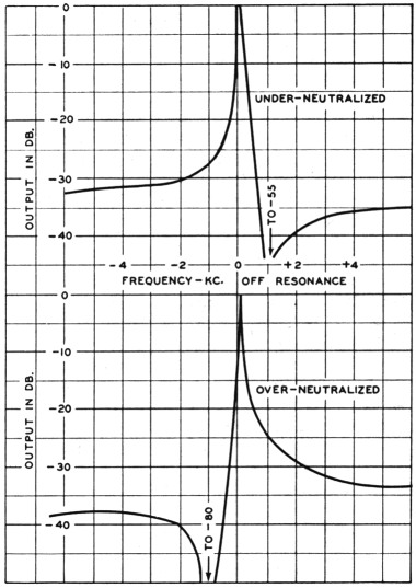
Fig. 1. Typical frequency-response curves of an oHneutrajized crystal filter with rejection notch set 1 kc. above resonance (upper curve) and below resonance (lower curve). (From M. G. Crosby, Proc. IRE, February, 1939.)
The fact is that once the intriguing objective of obtaining a small improvement in signal-to-noise ratio is replaced by the simple one of getting good f.m. detection, the means is to be found right in every good a.m. communications receiver. Crosby has pointed out 2 that an off-neutralized crystal filter converts phase modulation to amplitude modulation, and the practical difference between phase and frequency modulation is simply the audio-response characteristic. When the phasing condenser in a crystal filter is set to neutralize the crystal-holder capacitance exactly, the crystal has an essentially symmetrical resonance curve just like any tuned circuit. However, if the phasing capacitance is slightly too small or too large, the resonance curves take the form shown in Fig. 1. The well-known rejection notch appears, either above or below the resonant point depending on whether the phasing capacitance is too small or too large, and the response on the side on which the notch is placed is reduced in comparison to the response on the other side. The point to note about these curves (which are for the crystal filter alone, without any other i.f. selectivity) is that the response drops rapidly at first as the frequency is moved away from resonance, but then flattens off. Over a moderate frequency range the energy transfer off resonance will be substantially constant, assuming that the output circuit (that is, the circuit - into which the crystal filter works) is not in itself highly selective. Insofar as the crystal filter itself is concerned, this characteristic results in substantially uniform transmission of sidebands in a modulated signal when the carrier is tuned to the crystal peak. There is no progressive cutting of sidebands as the modulation frequencies become higher provided the filter is adjusted to be as sharp as possible. With a broad filter the lower frequencies are allowed to get through with greater amplitude and hence are accentuated in the final audio response. Inasmuch as the response is greater on the side of resonance opposite to that on which the phasing notch is placed, a form of single-sideband reception results. This characteristic, useful in a.m. reception through interference, also is helpful in converting f.m. to a.m.
However, an off-neutralized filter is responsible for another effect. Off the resonance peak the filter acts as a reactance, while at resonance it looks like a comparatively low series resistance. The consequence is that if the carrier is tuned to the peak, the phase of the sidebands (which are off the peak) is shifted with respect to the carrier by 90 degrees. This 90-degree phase shift will convert phase modulation into amplitude modulation. It will also convert frequency modulation into amplitude modulation, but because of the difference between phase and frequency modulation with respect to the a.f. characteristic, frequency modulation comes out with the lower frequencies accentuated while a phase-modulated signal comes out with the audio frequencies in their proper proportions.
There is nothing makeshift about this method of converting f.m. or p.m. into a.m. Since every good a.m. communications receiver has a crystal filter, no special equipment is required for n.f.m. reception. What is required is the development of an operating technique. In the first place, the filter should be set to the sharpest position and the carrier should be tuned in on the crystal peak, not set off to one side. The phasing condenser should be set not for exact neutralization but to give a rejection notch at some convenient side frequency such as 1000 cycles off resonance. There is considerable attentuation of the side-bands with such tuning, but it is not selective attenuation except for the added selectivity of the i.f. amplifier, and it can readily be overcome by using additional audio gain.
The fact that a crystal filter so used is inherently a phase-modulation detector rather than an f.m. detector brings up the question of p.m. versus a.m. at the frequencies at which this type of detection will be used. The argument that the means of reception is already at hand. without modification, in every good a.m. communications receiver strikes us as being a potent one for p.m. rather than f.m. There are at least two others on the side of p.m.: If the carrier frequency is to be stabilized - which is certainly essential in lowfrequency Operation - phase modulation is the natural method, and is simpler than any of the stabilized reactance-modulator methods we have seen. (It is questionable whether reactance modulation applied to a crystal oscillator actually results in frequency modulation. The "stiffness" of the crystal and the easily-demonstrated fact that sufficiently large frequency changes cannot be obtained on a static basis by varying reactances in the oscillator circuit indicate that phase modulation rather than frequency modulation is actually what takes place.) The other argument in favor of phase modulation is that, as demon, strated by Crosby in the same paper,2 it is less affected by selective fading in long-distance transmission than is frequency modulation. Changing from one system to the other involves nothing more serious than proper shaping of the audio-frequency characteristic, but it so happens that no special shaping is necessary in the transmitter's speech amplifier if phase-modulated output is desired from a phase-modulation system, nor is any a.f. compensation required in. a crystal-filter receiver if the incoming signal is phase-modulated. Phase modulation thus represents fewer complications in low-frequency work, in addition to promising better long-distance communication than f.m.