Finding the inductance of R.F. coils
The grid-dip oscillator for convenient measurement.
Among the collection of gadgets that is to be found in every ham station that has got beyond the bare transmitter-receiver stage there certainly ought to be a grid-dip meter. Like a voltohmmeter and a "Little Gem," it's so useful that once you have one you'll consider it indispensable. Measuring inductance values is just one of its applications.
High-school algebra teaches that if we know two of the unknowns in a formula containing three, we can find the third by transposing the formula: This principle is the basis of many present-day test instruments.
The resonant frequency of a circuit is determined by two factors, the inductance and the capacitance constituting the circuit, and can be found from the formula
![]()
The solution of the equation frequently is expressed in various forms that require little or no arithmetical work: for example, nomographs such as the one in the ARRL Handbook, slide rules and calculators of various types, tables of LC products at different frequencies, and so on. The principle, either with or without the aids to calculation, offers a simple way to determine the one quantity, inductance, that is generally known to a lesser degree of accuracy than the other two quantities.
In laboratories, inductance is generally measured on a Q-meter or on an r.f. bridge. These instruments are quite costly and cannot be made in the low-priced field. Therefore, the amateur must turn to some other method. A generally accepted device is the grid-dip oscillator.
The principle of the grid-dip oscillator is based on the fact that an LC circuit tuned to resonance with a self-excited oscillator and coupled to the oscillator inductance draws power from the oscillator. Because the oscillator is then supplying power to a load, less power is fed back from the plate to the grid to sustain oscillations. This results in a decrease in the grid current of the oscillator.
| C1 | 140 pF variable (Hammarlund MC-140-M). |
| C2 | 35 pF variable (Hammarlund MC-35-2). |
| C3 | 100 pF mica. |
| C4,C5 | 0.005 µfd. mica. |
| C6 | 16 µF electrolytic, 450 volts. |
| C7 | 8 µF electrolytic, 450 volts. |
| C8 | 140 pF variable, s.l.c. |
| C9 | 50 pF mica. |
| C10 | 75 pF mica. |
| C11 | 100 pF mica. |
| C12 | 200 pF mica. |
| R1 | 75 kΩ ½ watt. |
| R2 | 1 kΩ wire-wound potentiometer. |
| R3 | 25 kΩ, 10 watts, adjustable (set screen voltage at approximately 100 volts). |
| J | Tip jack. |
| MA | 0-1 ma. d.c. mA. |
| RFC | 2.5 mH r.f. choke. |
| S1,S2 | Ceramic wafer switch, 1 pole, 5 positions. |
| S3 | S.p.s.t. toggle. |
| T1 | Receiver-type power transformer, 250 v. each side c.t. at 50 ma., approx. |
| L3 | No. 1 43 turns No. 22 s.c.c. on 1¼ inch diam. form, tapped at 10th turn from ground. No. 2 18 turns No. 14 enameled, on 1½ inch diam. form, tapped at 8th turn from ground. No. 3 8 turns No. 18 d.c.c. on 1%-inch diam. form, tapped 2% turns from ground. |
| L2,L3 | 16 H, 50 mA. |
| S2 Position | Coil No. | Frequency Range |
|---|---|---|
| 1 | 1 | 2000 to 4400 kc. |
| 2 | 2 | 3900 to 8100 kc. |
| 3 | 3 | 7.1 to 15.25 Mc. |
| 4 | 3 | 11.25 to 15.6 Mc. |
| 5 | 2 | 6.1 to 8.3Mc. |
With this method of measurement it is necessary to know the oscillator frequency and the capacitance required to resonate the unknown coil to that frequency. An oscillator easily can be calibrated for frequency by methods that are well known to most amateurs.(1) The condenser is a little harder to calibrate, but a sufficiently-good calibration can be obtained by methods to be described later.
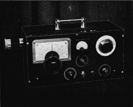
The instrument pictured offers a convenient and quite accurate means for measuring r.f. inductance values. It consists basically of an electron-coupled oscillator variable from 2000 kc. to 16 Mc., and a standard condenser with a group of shunts to extend its range.
The oscillator circuit, Fig. 1, employs the usual Hartley-type frequency-determining tank, which permits the condenser rotor to be placed at ground potential with consequent elimination of hand-capacity effects in tuning. Provision is made for obtaining r.f. output from the oscillator plate circuit, with the 1000-ohm potentiometer, R2, offering a means for adjusting the output voltage. This is useful for lining up receivers. When using the unit for this purpose a metal shield is placed over the oscillator coil and electrically connected to the cabinet to avoid pick-up from the coil.
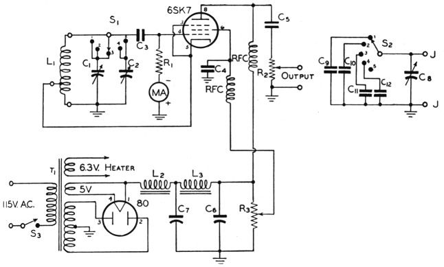
Fig. 1. Circuit diagram of the grid-dip oscillator.
The oscillator and its power supply are built on a 13½ × 5½ × 2-inch chassis and are enclosed in a 7 × 15 × 7½-inch cabinet. The parts layout shown in the photographs was selected chiefly from the standpoint of convenience in operating. The number of holes to be drilled is not large. Two of them, one carrying the lead from the standard condenser to the shunt switch and the other the grid lead from the tuned circuit to the 6SK7, should be insulated with ceramic grommets.
It will be noticed that on bandswitch Positions 4 and 5, Coils 3 and 2 (L1) respectively, are tuned by a 35-pMfd. variable. This was done to expand these parts of the range which include the 7- and 14-Mc. bands.
The coils plug into a ceramic socket on the side of the unit. In this position they radiate appreciably when not shielded, and the signal can be picked up on a receiver with no connection to the oscillator, permitting accurate measurement of the oscillator frequency with a multivibrator-type frequency standard if available. This would be desirable for accurate measurements.
The standard condenser (C8) should be a straight-line-capacity unit; the one used is a Cardwell ZU-140-AS. Shunts permit increasing the standard capacity to resonate coils over a wide range. The ideal method of calibration would be to use an r.f. bridge, but the ham seldom has access to this instrument. However, he can generally obtain a serviceman's capacity bridge. To obtain a reasonably accurate calibration from this instrument it is best to measure the condenser capacitance along several parts of the bridge scale. This is done by first measuring the capacitance for different dial settings with the condenser connected directly across the bridge. A graph is then drawn for this measurement. Then a capacitance of known value is connected in parallel with the condenser to be calibrated and the capacitance values measured again. Another graph is drawn subtracting the known capacitance value from each reading. Although the serviceman's bridge may be off a little as to direct scale reading, it is generally correct in its variation along the scale. The graphs will show the condition of the bridge calibration and thus permit a better calibration of the standard condenser to be made.
Measuring inductance
In making measurements, the coil of unknown inductance is connected to the two pin jacks indicated at J in Fig. 1. The coil is then placed in close-enough proximity to the oscillator coil to give a pronounced dip in grid current when C8 is tuned to the frequency to which the oscillator is set. An oscillator frequency must be chosen at which the coil can be expected to resonate with the standard condensers in the unit; this is not hard to do because of the rather large capacitance range. The instrument will give a good dip with high-Q coils at distances of several feet.
With the unknown connected and the oscillator frequency chosen and set, the standard condenser is varied until the grid-current reading dips. This indicates that the tank formed by the unknown coil and standard condenser are in resonance at the frequency of the oscillator. Knowing the frequency and the resonating capacity, it is a simple matter to transpose the resonant frequency formula and find the inductance, or it can be found from LC tables or an ARRL Lightning Calculator. Actually, the value so found is the "effective" inductance at the oscillator frequency and includes the padding effect of the distributed capacitance of the coil. However, the true inductance usually differs from the measured inductance by such a small amount that the discrepancy is well within the normal errors in measurement.
When measuring coils, particularly those with small values of inductance, remember to keep the leads to the standard condensers as short as possible, since the lead inductance adds to the coil inductance and thus makes the measured value slightly high.
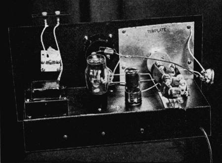
A view of the chassis arrangement. It was necessary to dismount the pin jacks and coil socket from the cabinet to take this picture.
Other applications
Many other uses for the instrument will be apparent. The calibrated condensers can be substituted quickly when servicing, in place of one thought bad. The oscillator can be used as a signal generator, provided a shield is placed over the coil on the unit.
Another practical use of the instrument is the determining of the resonant points of radio-frequency chokes. Each r.f. choke has distributed capacitance which resonates with its inductance at certain points, and both series and parallel resonance can occur. The choke may burn up if used at the parallel-resonant frequencies in a transmitter because of the high circulating current. At series resonance the choke presents no appreciable impedance and consequently completely fails its purpose.
The parallel resonance points can be determined by placing the choke in close proximity to the oscillator coil and varying the oscillator frequency until a pronounced dip occurs in the grid current. It must be remembered when varying the oscillator frequency over one of its ranges that the grid current also will vary across the range, but this variation is easily distinguished from the resonance dip. To determine the series resonance points it will be necessary to short the choke leads so the choke can absorb power from the oscillator with the parallel-resonant circuit shorted. The choke to be measured should not be held in the hand because body-capacity effects will change the resonant points.
The unit also provides a very quick and convenient method of checking the resonant frequencies of antennas. For example, the fundamental frequency of a half-wave center-fed antenna can be measured by lowering the antenna and tying it together at the center with a small shorting loop loosely coupled to the oscillator coil on the instrument. The oscillator frequency is varied until a dip is obtained. The frequency of the oscillator can then be measured by any of the usual means. Harmonic resonance can be similarly checked.
Notes
Robert M. Crotinger, W0GUY.