Overmodulation splatter suppression
A new method for preventing spurious sidebands.
The cause of over-modulation splatter is the sudden break in the modulation envelope when the carrier is swung down to the zero axis. Here is a system that fills in the over modulation "gaps" in the carrier and thereby prevents generation of spurious sidebands. There is no theoretical limit to the usable percentage of modulation if suitable means are used to receive the signal.
It is well known that overmodulation of conventional a.m. radiophone transmitters produces strong adjacent-channel interference aptly called "splatter." For this reason considerable effort has been expended on devising methods of preventing overmodulation - such as peak-limiting amplifiers and clipping circuits - to keep the channel space occupied by a given transmitter at a minimum. The purpose of this article is to describe a different approach to the problem; one in which the basic mechanism of splatter formation is analyzed, and a remedy worked out on the basis of this analysis. The result is a technique by which the percentage of modulation of any plate-amplitude-modulated 'phone transmitter may be allowed to exceed 100 by any desired amount, without any accompanying increase in channel bandwidth.
The least channel width that can be occupied by an a.m. transmitter is a band of frequencies extending above and below the carrier frequency by an amount equal to the highest modulating frequency that is to be transmitted. Voice transmission of high intelligibility is obtained when speech frequencies up to 2500 or 3000 cycles are transmitted; a voice radiophone need therefore occupy a channel only 6 kilocycles wide at the maximum. It is assumed that any sideband frequencies appearing outside the limits set by the carrier plus and minus the highest modulating frequency aie undesirable, since such sidebands cause interference to stations operating on adjacent channels.
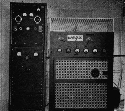
The transmitter at W6YX, in which the splatter-suppression circuit is incorporated.
Sidebands lying outside the normal channel occupied by an a.m. station are usually caused (1) by incidental f.m. or p.m. on the carrier frequency, or (2) by some form of amplitude distortion in the a.m. characteristic. This amplitude distortion may be composed of any or all of the following: (a) nonlinear distortion in the audio system, (b) nonlinearity of the modulated Class C r.f. amplifier, and (c) overmodulation.
All three are essentially similar in their effects. Just as amplitude distortion in the audio end produces harmonics higher than the highest undistorted audio frequency present, and therefore produces sidebands lying outside the normal channel, so amplitude distortion or overmodulation in the r.f. end also gives rise to sidebands falling in adjacent channels. There is no difference in either the theoretical analysis or the practical effects between the case where an audio signal containing higher-order harmonics is allowed to modulate a perfectly-linear Class C stage, thus producing higher-order sidebands and splatter, or the case where the audio is clean and distortion occurring in the r.f. end produces the same higher-order sidebands and splatter. The user of an adjacent channel would not be able to tell which type of distortion was producing the interference!
However, overmodulation differs from the other forms of amplitude distortion in that its onset is so abrupt. Assuming no audio or r.f. amplitude distortion, and a percentage of modulation less than 100, there will be no spurious sidebands at all, yet if the percentage of modulation exceeds 100 by only a little, vicious splatter appears. The reason for the sudden appearance of these unwanted sidebands is to be found in the sharpness of the bend in the waveform of the r.f. envelope at the zero axis, when overmodulation occurs. As is well known, any waveform having' a sharp or rectangular bend must be composed of many harmonics, which in this case manifest themselves as higher-order sidebands. A square wave, for example, has appreciable harmonic components up to the tenth; if a transmitter were so badly overmodulated with a sine wave that at least part of the waveform looked square, we might expect to find at least ten strong pairs of sidebands on both sides of the carrier. If the modulating voltage producing this approximation to a square wave had a frequency of 3000 cycles, the bandwidth of the signal would then be of the order of 60 kc.!
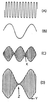
Fig. 1. A Steady carrier wave, Eo sin 2πft.
B Audio-frequency voltage, m sin 2πfst (m = 1).
C Product of A and B: Eom sin 2πft sin 2πfst (during audio-frequency halfcycle X phase of carrier voltage is 180 degrees different from that of adjacent half-cycles).
D Sum of A and C: e = Eo sin 2πft + Eom sin 2πft sin 2πfst = 100% amplitude-modulated wave (phase of carrier constant throughout audio cycle) (A and C add at Y and cancel at Z).
Now let us see what happens when distortion occurs in the audio end of a transmitter. High-level plate modulation, now almost universally used, fortunately interposes a modulation transformer between the audio system and the modulated Class C amplifier. This transformer acts as a low-pass filter so far as the higher audio harmonics are concerned, and simply removes them before they can do any damage. If we have a square wave at a low audio frequency (say 100 cycles) the waveform will be passed by the modulator with its squareness preserved because the tenth harmonic is only 1000 cycles. Note that the corresponding sidebands do not spill outside the normal channel. But if the frequency of the square Wave were raised to 3000 cycles the modulation transformer would have to pass 30 kc. in order to preserve the waveform. Since most modulation transformers designed for amateur use fall off in response rather rapidly above 5000 cycles, the waveform reaching the Class C amplifier for a 3000-cycle square-wave input will be much more nearly sinusoidal than square, and the spurious sidebands will be correspondingly reduced in amplitude. For this reason, audio distortion is by no means as troublesome a source of adjacent-channel interference as overmodulation.
To recapitulate, overmodulation causes sharp edges or bends in the waveform of the envelope of the transmitted signal, regardless of the audio frequency at which the overmodulation takes place, and there is nothing to prevent the radiation of the spurious sidebands thus generated. Overmodulation, therefore, is bad. Let us now see what can be done about it.
The theoretical basis
A good starting point is the conventional equation of a sinusoidally-modulated wave:(1)
![]()
where
e = instantaneous amplitude of wave,
Eo = average amplitude of wave,
fs = modulating frequency,
f = radio frequency, and
m = degree of modulation, defined as
![]()
where Emax is the maximum envelope amplitude. Suppose we multiply Equation 1 out. We get:
![]()
The first of the two expressions on the right-hand side of this equation is clearly equal to the carrier voltage. The second expression has a term equal to the carrier voltage, multiplied by the quantity sin 2trft. In addition, the amplitude of this expression as a whole is also controlled by the arbitrarily-selected constant, m. For a given m, we may consider the carrier component of the second term (Bo sin 27rft) to be acted upon or modulated by the audio component (sin 24.0. As time goes on, and the t in this equation increases, the quantity sin 27rf1 varies sinusoidally between minus one, zero, and plus one, as does the sine of any angle. This implies that the polarity of the carrier voltage represented by the right-hand expression of Equation 2 changes by 180 degrees from one half-cycle of audio modulation to the next, since a 180-degree phase change is represented by a change in sign. We may then think of an amplitude-modulated wave as being in reality made up of two components: a steady component of carrier frequency, and a varying component of carrier frequency which reverses phase on alternate audio half-cycles. Thus when the two components are phased alike, they add, and we have upward modulation; when the phase of the varying component changes by 180 degrees, the two components cancel each other and we have downward modulation. Fig. 1 illustrates this action.
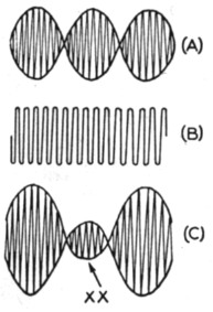
Fig. 2. A Same as Fig. 1-C.
B Steady carrier, similar to Fig. 1-A, but weaker.
C Sum of 2-A and 2-B (at XX2-A exceeds 2-B, and r.f. carrier is 180 degrees out of phase with that of adjacent portions of wave).
Let us look at Equation 2 again. It will be seen that there is no basic 'reason why the arbitrary constant m should be no larger than 1; the mathematics are not changed in the least if m is made equal to 5 or 10 instead of 1. Certainly increasing m does not bring in any additional frequencies such as would have to be present if any flattening or distortion occurred. If m increases above 1, we simply have a larger ratio of sidebands to carrier than before; the sidebands themselves are unaffected. It will be remembered that a balanced modulator circuit can be made to eliminate the carrier completely, leaving the sidebands intact, so the possibility of increasing the sideband-tocarrier power ratio above one-half, without introducing distortion, seems reasonable. Let us investigate graphically what happens if m, in Equation 2, is allowed to increase above 1. The result is plotted in Fig. 2-C. Since the right-hand term of Equation 2 now more than cancels the left-hand term, we find the phase 4of the total radiated signal changing by 180 degrees during a portion of the audio cycle. This section of the waveform, where the r.f. voltage of reversed phase appears, is that portion where there is no output at all in the case of ordinary overmodulation.
Now to make an ordinary plate-modulated - radio transmitter produce an r.f. waveform similar to that of Fig. 2-C, it is only necessary to provide some means of supplying the tank circuit with r.f. voltage 180 degrees out of phase with that of the carrier, during that portion of the audio cycle when overmodulation makes the plates of the regular Class C amplifier tubes negative with respect to ground. A circuit for doing this is shown in Fig. 3.
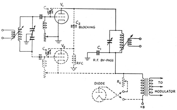
Fig. 3. The basic splatter-suppression circuit.
Splatter-free circuit
Tube V1 is a conventional single-ended Class C amplifier tube. Tube V2, the "splatter-suppressor" stage, and its associated circuit components are drawn with dotted lines for the sake of clarity. Tube V2 is shunt-fed in both grid and plate circuits. The plate of V2 is grounded through the r.f. choke so far as d.c. is concerned, but is effectively tied to the plate of V1 for r.f. by blocking condenser C2. The cathode of V2 is connected to the positive high-voltage lead from the modulator, consequently a filament transformer of low capacitance to ground and adequate insulation must be used. Cl serves as an r.f. by-pass both for the tank coil and for the cathode of V2. This condenser should be large enough to give good r.f. bypassing, but not so large that it and the capacitance to ground of the filament transformer supplying V2 appreciably affect the high-frequency response of the modulator.
So long as the instantaneous plate voltage at the upper terminal of the modulation-transformer secondary winding remains positive, V1 will operate in the normal way and deliver r.f. of given phase to the load. When overmodulation occurs and the supply potential of V1 is driven negative, V2 comes into action and delivers r.f. of opposite polarity to the load, thus satisfying the conditions of Fig. 2-C. Assuming linear operation throughout, splatterless overmodulation results.
There are one or two other points of interest in connection with Fig. 3. Since V2 is shunt-fed in both grid and plate circuits, r.f. chokes of widely-different inductance values must be used if low-frequency- parasitics are to be avoided. It will be noticed that V1 and V2 effectively neutralize each other. If both tubes have the same grid-plate capacitance, neutralizing condensers Cx could be omitted, assuming the circuit were laid out perfectly symmetrically. Actually, a small neutralizing capacitor would probably have to be connected between grid and plate of one tube or the other, in order to compensate for unbalance because of stray 'circuit capacitances. If dissimilar tubes are used, as is perfectly possible, the neutralizing condenser is connected from grid to plate of the tube having the lesser grid-plate capacitance, and need have a maximum value only slightly greater than the difference between the capacitances of the two tubes.
The grid-bias resistors of V1 and V2 are shown as being variable; this makes it possible to "balance" two tubes whose characteristics are not alike. The object is to arrange matters in such a way that the same r.f. output (irrespective of phase) is produced by the same plate-supply voltage, either positive or negative in polarity. It is also desirable to have the modulator work into the same load impedance no matter which tube, V1 or V2, is supplying the r.f. output. The easiest way to make sure the r.f. outputs are equal is to make use of the well-known trapezoidal oscilloscope pattern, for which r.f. voltage is applied to the vertical plates and a.f. voltage to the horizontal plates. Fig. 4-B shows a situation which might well be encountered; the suppressor tube is not as efficient as the carrier tube and is not producing the same output at the same plate voltage. Variation of the grid-bias resistors of the two tubes in Fig. 3 should make it possible to equalize the two halves of the pattern as in Fig. 4-C: The biases of the two tubes must always be kept high enough to ensure Class C operation, of course.
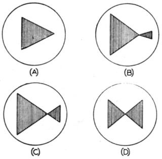
Fig. 4. Trapezoidal oscilloscope patterns of system's operation:
A - conventional 100% modulation;
B - overmodulation, suppressor tube supplying less output than carrier tube;
C - overmodulation, suppressor-tube characteristic matched to carrier-tube characteristic;
D - no carrier radiated - pure side-bands only (percentage of modulation equals infinity).
If V1 and V2 are widely dissimilar tubes, it may be that after they are adjusted for the same r.f. output voltage at the same d.c. supply voltage they will not offer the same load impedance `(ratio of d.c. volts to d.c. amperes) to the modulator. If the modulator has poor voltage regulation (and most do) distortion of the output waveshape will result. As an example, Fig. 5 shows a waveform which might occur if the load impedance offered by the suppressor tube were much less than that offered by the carrier tube. The remedy is to connect a diode and a resistance as shown in Fig. 3. The diode simply acts to switch the compensating resistance R. in or out of the circuit at the same time the suppressor tube goes in and out of action. The object is to connect the diode in such a polarity that the compensating resistance is effectively in shunt with the tube - carrier or suppressor - that offers the higher load impedance to the modulator. The compensating resistor is then adjusted until the effective load impedances are the same. In this way the load presented to the modulator may be made constant over the entire audio cycle and distortion of the audio waveshape is avoided.
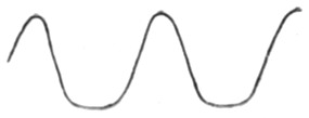
Fig. 5. Distortion of modulator output waveform which might result if suppressor tube represents lower load impedance than carrier tube (mild over-modulation).
Bringing the tubes into balance will be easier, the more nearly alike they are. However, since overmodulation will normally occur during a relatively small portion of the audio cycle, the average power input, tq the suppressor tube will be small and this tube need have a plate dissipation rating only a fraction of that of the carrier tube, provided it has adequate insulation and peak-power capacity. In' selecting a suppressor tube it is desirable to find one whose characteristics are as nearly like those of the carrier tube as possible, except in point of plate-dissipation rating. For example, a 100-TH would serve as an excellent suppressor tube for a 250-TH; it has very nearly the same , same ;a and is, in effect, ascaleddown 250-TH. If dissimilar tubes must be used, it is usually best to pick for the suppressor tube one whose plate resistance is lower than that of the carrier tube rather than the reverse, for the reason that it may otherwise be difficult to get adequate output from the suppressor tube. A 100-TH, for example, would be difficult to use as a suppressor tube with a 304-TL, because both must produce the same output at the same plate voltage. The 100-TH would have to be driven very hard in order to operate as efficiently as a 304-TL, and before the desired condition was reached it might be that the rated grid dissipation of the 100-TH would have to be exceeded. A 75-TL, on the other hand, would be more practical since its characteristics are more nearly like those of the 304-TL.
It is obvious that full advantage of this system of overmodulation splatter suppression cannot be taken unless the modulator has adequate power capacity to take care of the extra demand when overmodulation takes place. In this connection, It should be remembered that the required modulator power varies as the square of the degree of modulation; hence to modulate 200 per cent, four times the audio power needed for 100-per-cent modulation is required. A 1 kW station modulated 200 per cent would require 2000 watts of audio power. The average power input to the suppressor tube may easily be calculated on the basis of the percentage of time during which it is in operation; a plot of the result appears in Fig. 6. The extra power input to the carrier tube is also considerable, and may be calculated by figuring the total modulator power for the percentage of overmodulation desired, as above, and then subtracting from it the power input to the suppressor tube taken from Fig. 6. Thus if we have a 1 kW phone transmitter modulated 200 per cent, the modulator power is 2000 watts and the input to the suppressor tube is 670 watts, leaving 1330 watts which must be handled, along with the 1 kilowatt of carrier, by the carrier tube or tubes. These power-handling requirements sound excessive until it is remembered that the sideband power generated when a 1 kW phone is modulated 200 per cent is equal to that generated when a 4 kW phone is modulated 100 per cent.
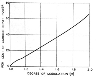
Fig. 6. Average power input to suppressor tube as a function of degree of (over)modulation for a sine-wave modulating voltage.
When the ordinary radiophone transmitter is voice-modulated, the normal procedure is to set the audio gain to the point at which overmodulation occurs on peaks. From that point on, the operator must engage in a struggle with his conscience to decide how often overmodulation on peaks may permissibly take place. The higher the gain-control setting, the louder the signal, but the more frequent the overmodulation. With the splatter-suppression circuit described in this article, and sufficient reserve modulator capacity, he may increase gain until overmodulation occurs much more frequently, without setting up splatter and running the risk of a green QSL card from the FCC. A meter in series with the plate-supply lead of the splatter-suppression tube can be used as an indication of overmodulation; however, it cannot be relied upon to give a warning of the overload point of the splatter-suppression system itself. For that purpose an oscilloscope is doubtless the best indication, although metering systems can readily be devised. The 'scope should be connected to indicate either r.f. or a.f. waveshape - whichever overloads first. With a little practice, flattening of the waveform can be quite readily detected even when a complex speech wave is present. Alternatively, the maximum deflection before overloading can readily be calibrated by whistling a sine wave into the microphone, and then placing suitable markers on the face of the cathode-ray tube. The gain should then be so set that the very loudest peaks fall short of these markers.
Reception
It should be pointed out that a signal overmodulated as shown in Fig. 4-C will be distorted when detected in a receiver using a linear second detector. The action is illustrated in Fig. 7-B. Note that, although an overmodulated 'signal of this type results in audio distortion when detected, there is nevertheless no distortion present in the r.f. signal itself, and hence no spurious sidebands. It will be found that audio distortion of the type shown in Fig. 7-B sounds somewhat worse to the ear than that resulting from ordinary overmodulation, illustrated in Fig. 7-D. A Fourier analysis of the waveforms would undoubtedly show that of Fig. 7-B to be richer in harmonics and poorer in fundamental than that of Fig. 7-D.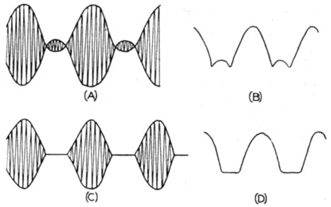
Fig. 7. Illustrating receiver distortion:
A - envelope of overmodulated wave;
B - distorted audio signal produced when A is demodulated;
C - envelope of distorted overmodulated wave;
D - distorted audio signal produced when C is demodulated.
Now an overmodulated wave such as that of Fig. 7-A merely represents a signal whose side-bands are stronger than those required for 100per-cent modulation. If by some means these side-bands can be reduced in strength before they reach the second detector of a receiver (the carrier remaining the same) the combined signal will no longer be modulated as heavily; in fact, it may not be overmodulated at all. This gives a means of reducing the distortion resulting from the linear detection of a signal such as that of Fig. 7-A; it is only necessary to switch in the crystal filter of a communications receiver and adjust it for a narrow i.f. passband. At the higher audio frequencies the i.f. selectivity of the receiver will then tend to reject the excess sidebands, and as soon as the signal'reaching the second detector is no longer overmodulated, the distortion disappears.
This effect was first noticed during the course of some laboratory tests of the system. As received on a conventional communications receiver adjusted for the widest i.f. bandwidth, the overmodulated signal sounded distorted but understandable. As the crystal filter was switched in and adjusted for a progressively narrower bandwidth, a point was found at which the distortion very Iargely disappeared, indicating that the signal reaching the second detector of the receiver was no longer badly overmodulated. The speech quality under these conditions sounded drummy but very nearly undistorted. Since this situation resulted from an excess of low audio frequencies rather than from a shortage of highs, the proper compensation could easily have been obtained by providing the receiver with a tone control that reduces the response to the lower audio frequencies. The audio compensation needed at the receiver, could, of course, have been avoided by high-frequency preëmphasis at the transmitter.(2)
It is believed that such an arrangement has interesting possibilities, for voice communication where a maximum of intelligence is to be transmitted on a carrier of given strength. Increased receiver selectivity, of course, results in an improved signal-to-noise ratio and a reduction in interference from stations operating on nearby channels. At the same time the extra sideband power at the transmitter is obtained without the necessity of generating carrier power to go along with it. It should be noted that adding the over-modulation circuit to the transmitter does not affect the tuning adjustments associated with frequency changing in any way.
A practical amplifier
Fig. 8 is the circuit diagram of a typical final amplifier arranged for overmodulation splatter suppression. Cross-connected push-pull splattersuppression tubes are used in order to preserve the symmetry and balance to ground. HK-254 tubes were selected as suppressors because they happened to be available and have amplification factors and grid-plate capacitances similar to those of the 250-THs. They have much more plate-dissipation capacity than needed; for the service intended (suppression of incidental over-modulation on peaks) much smaller tubes, such as 35-TGs or HK-24Gs, would have been adequate.
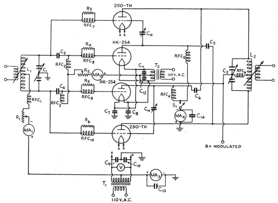
Fig. 8. Splatter-suppressing final-amplifier circuit used at W6YX.
| C1 | 75 pF per section, 2000 volts. |
| C2 | 100 pF per section, 10,000 volts. |
| C3,C4 | 0.002 µF mica, 2000 volts. |
| C5,C6 | 0.002 µF mica, 12,500 volts. |
| C7,C8 | 0.002 µF mica, 5000 volts. |
| C9-C14, inc. | 0.002 µF mica, 500 volts. |
| Cn | National NC-800 with bottom plate removed (see text). |
| R1 | 1500 Ω adjustable, 100 watts. |
| R2 | 5000 Ω adjustable, 50 watts. |
| R3,R4,R5,R6 | 50 Ω carbon, 10 watts. |
| L1 | 28 Mc. 3 turns No. 12 enam., 2 inches diam., center-tapped, 2-turn link. |
| L2 | 28 Mc. 2 turns ¼ inch copper tubing, 2 inches diam., center-tapped, 2-turn link. |
| MA1,MA4 | 0-300 mA d.c. |
| MA2 | 0-150 mA d.c. |
| MA3 | 0-1 A d.c. |
| RFC1,RFC2,RFC3 | 1 mH 600 mA choke (National R-154). |
| RFC4,RFC5,RFC5 | 1½ inch winding of No. 30 d.c.c. on ½ inch diameter ceramic form. |
| RFC7,RFC8,RFC9,RFC10 | 3 turns No. 14 wound on R3, R4, R5 and R6 respectively. |
| S1 | S.p.s.t. switch, high-voltage insulation. |
| T1 | Filament transformer, 5 volts, 20 A |
| T2 | Filament transformer, 5 volts, 25 A, open frame (low capacitance between primary and secondary). |
| V | 0-7.5 V a.c. |
Note: Coils for other bands should be designed to provide proper Q.
The circuit is conventional in design and layout in every way; the only departure from normal practice lies in the cross-connection and reversed-polarity shunt feed of the suppressor tubes. Filament power for the HK-254s is supplied by a surplus transformer, apparently designed for radar service,- having a secondary winding well spaced and insulated from the core. This results in an unusually low capacitance to ground, which allows the r.f. by-pass condensers C7 and C8 to be made proportionately larger before the frequency response of the modulator is affected. Use of a special transformer is generally not necessary, since the capacitance to ground of the average filament transformer secondary seems to be of the order of 0.002 µF. This is not excessive unless the modulator is working into an unusually-high load impedance.
Note that the grid-bias resistor of the HK-254s is connected back to the center-tap of their filament transformer. Partial fixed bias may be used with the 250-THs, if desired. None is necessary with the HK-254s because they draw plate current only when overmodulation occurs. The grid-current meter of the HK-254s should be adequately insulated from ground, of course, because it is normally at the full positive plate-supply voltage. Switch S1, which disconnects the splatter-suppression tubes and permits a check of the operation of the circuit, should be provided with high-voltage insulation and should be connected with the plate-current meter between it and ground, as shown in the diagram.
Because there is a difference of only a tenth of a micromicrofarad between the grid-plate capacitances of the HK-254s and the 250-THs, the tubes very nearly neutralize each other. In fact the minimum capacitance of the smallest available high-voltage neutralizing condenser was found to be too much, so the bottom plates were removed and the circuit wiring itself was used as the other half of each neutralizing condenser! Finding the point of perfect neutralization is done in the conventional way; when the circuit is neutralized for the carrier tubes it is also neutralized for the suppressor tubes.
The photographs show the final amplifier of Fig. 8 as set up for operation. The station is that of the Stanford University Radio Club (W6YX). The grid tank circuit is mounted inside its own shielded box, and the one-plate neutralizing condensers may be seen close to this box. Condensers C5 and C5 of Fig. 8 are mounted upside down on a wooden support so that the leads connecting them to the plates of the tubes are as short as possible. In this particular layout (which is by no means to be considered as exemplary!) ultrahigh-frequency parasitics were encountered but were eliminated by parasitic-suppressing chokes connected in the grid leads as shown in Fig. 8.
Tuning up the transmitter offers no particular difficulties. The grid-leak resistors, R1 and R2 are first adjusted until both carrier and suppressor tubes are drawing approximately the rated grid current with the available excitation. After the amplifier is neutralized, a positive plate voltage is applied, and the presence of parasitics in the carrier tubes investigated. When these are under control, the polarity of the plate supply is reversed, and the suppressor tubes are deparasited. Next, the plate-supply polarity is returned to normal, and the carrier tubes loaded into the antenna in the usual manner. The amplifier is then ready for an adjustment of the modulation characteristic with the aid of an oscilloscope connected to give a trapezoidal pattern.
For this test, no plate voltage (or carrier) is needed, since it is only necessary that overmodulation take place. The output of the modulator can be connected directly between the B+ terminal of the final amplifier and ground. Double sidebands alone will then be generated, and the pattern should look like that of Fig. 4-D. If it does not, the grid-bias resistors R1 and R2 should be adjusted until each half of the pattern is the mirror image of the other. Once this adjustment has been made, attention should be turned to the waveshape of the audio voltage out of the modulator.
Here an audio oscillator is desirable. If distortion such as that of Fig. 5 is encountered, it will be necessary to determine which tubes - carrier or suppressor - are offering the lower load impedance to the modulator. A simple way to do this is to reduce plate voltage, leaving the antenna loading fixed. Then, at the reduced voltage, the ratio of d.c. plate volts to d.c. plate current can be measured for both cartier and suppressor tubes. An equalizing tube and resistance, as shown in Fig. 3, can then be connected across the modulator output terminals in such a way that the extra resistance is effectively shunted across whichever blanch of the r.f. circuit shows the higher load impedance. For example, it might be found that the carrier tube represented a resistance of 400 volts divided by 100 ma., or 4000 ohms, when the suppressor tube represented a resistance of 400 volts divided by 125 ma., or 3200 ohms. It would then be necessary to shunt the carrier tube with a resistance of 16,000 ohms in order to make its effective impedance equal to 3200 ohms.. The cathode of the diode tube of Fig. 3 would then be connected to the lower side of the modulation transformer and the anode through the resistor to the upper half. The modulator would then have to be matched to the new load impedance of 3200 ohms.
If the carrier and suppressor tubes are identical, or have characteristics very nearly alike, balancing may not be necessary. However, when dissimilar tubes are used balancing will almost surely be required. For the load-equalizing diode, any convenient tube can be used except mercury-vapor rectifiers, which have short life when oper ated at frequencies in the audio range. Since the current through the equalizing resistance will be small and most of the modulator output voltage will appear as a drop across this resistance, receiving-type rectifier tubes such as the 5Z3 or the 5R4GY will be satisfactory unless extremely high audio voltages are involved. In this case a rectifier such as the RK-60, with plate connections brought out through the top of the bulb, would be desirable.
It is desirable to have a suppressor tube that can be made to be more efficient than the carrier tube. The equalizing resistance will then be effectively connected in shunt with the suppressor tube, and audio power will be wasted in this resistance only when overmodulation takes place. Fortunately it turns out that most suppressor tubes, being smaller than the carrier tubes, tend to be more efficient than their larger counterparts.
Some additional methods of bringing the suppressor and carrier tubes into balance will be found in another article by the author.(3)
Finally, a word of warning is in order. Since the splatter-suppression circuit involves tinkering with the r.f. end of a transmitter, where distortion is relatively more dangerous than in the audio end, the circuit should not be attempted unless adequate test and measuring equipment are available. It should certainly not be attempted by anyone inexperienced in radiotelephone adjustment procedure. Remember, too, that spurious sidebands can be caused by distortion anywhere in a transmitter. The suppression circuit definitely cannot take care of splatter whose source is audio distortion appearing at the output terminals of the modulator!
Remember, too, that as the amateur regulations now read, it is expressly forbidden to modulate in excess of 100 per cent. Since in all likelihood the intention behind this regulation was to prevent splatter and unnecessary channel width, it does not seem inconsistent with the spirit of the law to use the suppression circuit as a means of preventing splatter accompanying momentary overmodulation on peaks. But before rushing out to buy a 2 kW modulator to go with that 1 kW transmitter, better wait to find out how the FCC will define the maximum legal power input to a reduced-carrier double-sideband a.m. phone!
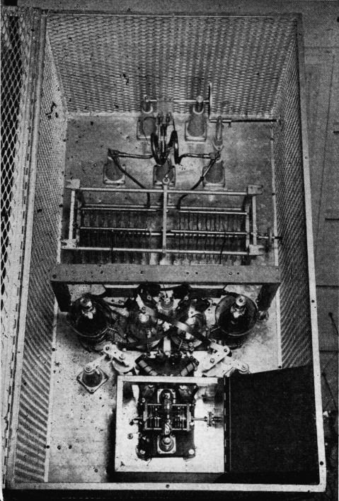
Layout of the final amplifier, showing the splatter-suppression tubes.
Acknowledgment
The assistance of various members of the Stanford Radio Club in constructing and testing the final amplifier described in this article is herewith gratefully acknowledged. Particular thanks are due Lester A. Roberts, W6YWX, Bertram G. Ryland, W6BEW, and Rodney O. Beaudette, W7FXI.
Notes
- See, for example, Terman's radio engineer's handbook, p. 352.
- It would seem that this system of modulation could be received with little distortion by the exalted-carrier method of reception with a crystal filter described in QST for May, 1947, p. 27, inasmuch as the transmitted signal is quite similar to the signals often received from a normally-modulated a.m. transmitter when selective fading exists. With a sharp off-neutralized filter little or no audio compensation is needed at either the transmitter or receiver for natural reproduction. - Ed.
- O. G. Villard, jr., "Overmodulation without Sideband Splatter," Electronics, January, 1947.
Oswald G. Villard, Jr., W6QYT.