A new noise-reducing system for C.W. reception
"Pulse detection" for elimination of impulse noise.
A new approach to the problem of ferreting out c.w. signals from noise. The noise is treated as something that is always existent and therefore is used as an energy source, while the signal is used to detract from that source. The signal is reproduced by a tone back-keyed by the energy during the keying spaces.
The detection system herein described is referred to as a "pulse detector," and it will soon be apparent to the reader that it differs basically from conventional c.w. reception systems. Pulse detection was developed to fulfill the long-sought requirement for clean demarkation of signals under conditions of heavy background interference such as is caused by manmade static in central areas of cities, as well as by severe atmospheric static. This article will not attempt to consider the application of the pulse detector for modulated-carrier reception.
In the approach to the problem it was reasoned that while electrical interference energy exists' at all times in a communications receiver, either from antenna pick-up or from front-end noise in the receiver, in contrast a c.w. signal has on and off intervals as well as fading characteristics. Also, while the interfering impulse noise may vary greatly in amplitude, the duration of the interfering impulses is much shorter than even highspeed c.w. characters.
In referring to impulse interference at the detector, it is necessary to consider these interferences as discontinuous wave trains whose effective time duration varies in accordance with the amplitude of the original impulse. It is these receiver-generated wave trains that cause portions of the intelligence waves to be obliterated from the detector when the amplitude or audio beat is being detected. In receiving locations having a high ambient impulse background noise it might seem these wave trains could be frequent enough to create a continuous wave if they followed each other very closely. However, considering that each wave train or circuit "ring" is started by an impulse, and that these impulses have no fixed phase relation to each other, it follows that the random phase relation will cause conflicting phase angles between wave trains. Since these phase differences cause the amplitude to fall between each pair of wave trains, the resulting disturbance therefore cannot form a continuous wave. This condition marks the distinction between reception of a continuous wave and reception of impulse wave trains at the detector circuit in receivers of conventional deqign.
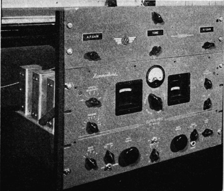
A pulse-detector unit constructed to operate with a Super-Pro receiver. The unit is complete with power supply and provides adjustable tone in the keyed circuit.
The detector voltage from the discontinuous wave trains may be considerably greater than the voltage from the continuous waves, which not only prevents the use of an a.v.c. system, but may also make it impossible to obtain a readable signal with ordinary b.f.o. detection.
This essential difference between a c.w. signal and random noise is illustrated in Fig. 1, where A, B and C show what might happen with a series of unrelated impulses. The r.f. noise at A is converted by the detector into a varying direct current as shown at B. When the detector output is coupled to a following audio stage the average d.c. component is eliminated by the coupling condenser, leaving only the audio-frequency a.c. signal shown at C. On the other hand, the c.w. signal shown at D is of - unvarying amplitude (assuming for the moment that it is not modulated in any respect and that there is no random noise present) and when rectified by the detector produces the steady direct current indicated at E. The unvarying d.c. output of the detector produces no response when coupled to the audio system through a coupling condenser, except at the times when the signal voltage rises or falls; i.e., when the signal is keyed. At these two times there is a key click if the rate of rise and decay of the signal is great enough to produce an audible response.
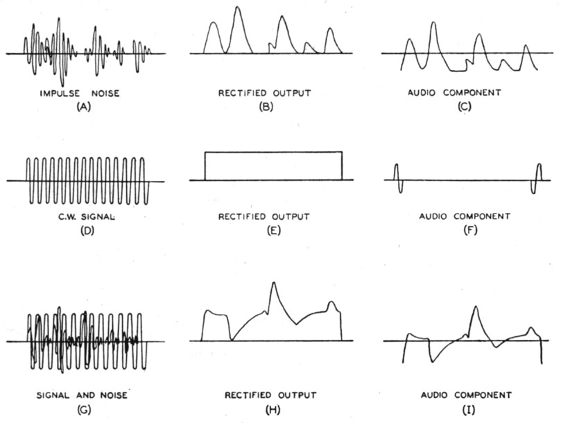
Fig. 1.
Upper line: R.f., rectified d.c., and audio component of noise alone.
Second line: Same for signal alone.
Third line: Signal and noise combined.
When both noise and signal are present, as in the lower row of drawings, the random phase relationship between the c.w. carrier and the impulse waves may result either in addition or partial cancellation of the carrier and noise. A typical case, after rectification, might be as shown in Fig. 1-H. The noise appears as an amplitude modulation on the c.w. carrier, and it is this noise modulation of the carrier that is the audio-frequency output of the detector.
Going now to Fig. 2, the impulse noise alone at A, when combined with a fading keyed c.w. signal as shown at B, might result in a rectified output of the form shown at C. The signal is unrecognizable in the rectified output; it is "buried" in the noise. However, if both noise and signal are drastically amplitude-limited as at D, with the limiting level set below the signal level represented by a deep fade, the voltage fluctuations when the c.w. signal is absent are greater than when it is present. The random phase relationship between the noise impulses and the carrier means that there is just as much chance that the carrier will be modulated upward as there is that it will be modulated downward. Since only the downward modulation is effective in producing audio-frequency output because of the heavy limiting, this means that there is less a.f. voltage from the detector during the c.w. interval than there is when the signal is absent; in other words, there is more a.f. energy during the keying spaces than during the marker intervals. This is indicated in Fig. 2-E. It is this difference in energy that forms the basis of pulse detection.
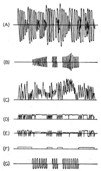
Fig. 2. Steps in the development of pulse detection. As explained in the text, the system makes use of the fact that there is a difference in the a.f. energy level when the carrier is present and when it is-not.
In the application of the system, the audio energy during keying spaces is amplified, limited, and rectified to produce a d.c. signal as shown at F in Fig. 2. This d.c. component is then used to control an audio tone generator, or to operate automatic equipment directly. "Back-contact" keying is necessary, of course, to follow the original signal with the audio tone as indicated at G.
A practical circuit
In the practical application of this system it has been found desirable to have two or three filter time-constant adjustments in the d.c. generating circuit. This permits various speeds of reception, so that even when, for example, 100 w.p.m. cannot be received because of very heavy impulse noise such as vehicle ignition interference, it is still quite satisfactory for perfect reception at 15 w.p.m. The tone frequency should be adjustable to prevent tiring the operator.
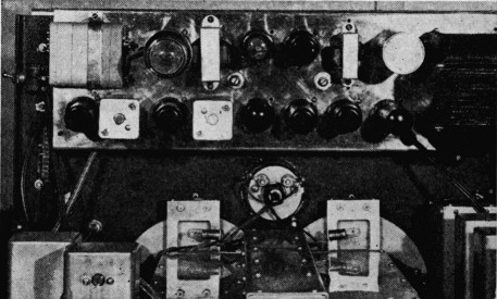
Chassis view of the pulse-detector unit. Ordinary practice should be followed in layout of the i.f. and audio circuits.
The circuit shown in Fig. 3 is adaptable for application to the second detector and audio end of a communications receiver. V1 is the detector and limiting diode for demodulation of the carrier wave when the amplitude is in excess of the effective bias on the second diode. V2 is an audio amplifier used to amplify the audio component of the noise between the marker intervals, and V3 is a limiting amplifier for holding the noise energy at a relatively constant value. The diode section of V4, which rectifies the noise energy, has three settings of filter capacitance to provide the three time constants mentioned above. The triode section of V4 is biased to cut-off by the d.c. from the diode, and Vs is a phase-shift audio oscillator that excites the grid of V4. V6 is the power-amplifier tube of the receiver. Switches Si and S3 permit the receiver to be operated in the normal phone position or for b.f.o. c.w. reception when there is no noise.
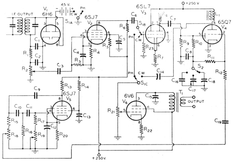
Fig. 3. Circuit diagram of pulse-detector unit.
| C1,C2 | 100 pF mica. |
| C3,C6,C9,C11 | 470 pF mica. |
| C4 | 25 µF electrolytic. |
| C5,C12,C13,C14 | 0.05 µF paper. |
| C7,C16 | 0.005 µF mica. |
| C8 | 0.003 µF mica. |
| C10,C19 | 0.001 µF mica. |
| C15,C18 | 0.02 µF paper. |
| C17 | 0.01 µF paper. |
| R1,R8,R13 | 47 kΩ, ½ watt. |
| R2,21 | 250 kΩ volume control. |
| R3,R6,R14,R17 | 470 kΩ, ½ watt. |
| R4 | 1400 Ω, ½ watt. |
| R5 | 2.2 MΩ, ½ watt. |
| R7 | 1500 Ω, ½ watt. |
| R9,R12,R15 | 100 kΩ, ½ watt. |
| R10,R11,R16,R23 | 220 kΩ, ½watt. |
| R18 | 100 MΩ volume control. |
| R19 | 1 MΩ volume control. |
| R20 | 470 Ω, ½ watt. |
| R22 | 330 Ω, 1 watt. |
| L1 | Audio choke 50 H or more. |
| S1 | 3 pole 2 position switch. |
| S2 | 1 pole 3 position switch. |
For best results, the a.v.c. should be off and the r.f. gain should be full on. The b.f.o. is not required. At least two i.f. stages are recommended, and a third will improve the results. When using a third i.f. amplifier, a 6SJ7 sharp cut-off pentode type should be used for limiting, as in f.m. receivers. The object of having so much gain is to permit the tone bias keying energy to be maintained from front-end noise in the receiver and thus make it unnecessary to rely on antenna noise to supply the operating energy. This also increases the threshold sensitivity of the detector.
To prevent interference from transmitters on adjacent channels the i.f. selectivity of the receiver should be high. However, the extreme selectivity represented by a sharp crystal filter cannot be used in the presence of strong impulse noice because in such a case the wave trains are lengthened to the extent that they compare in duration with code characters and consequently also key the tone oscillator. With the normal selectivity of a communications receiver this does not occur.
It is quite normal to get perfect reception from a c.w. signal that is not discernible through impulse noise on orthodox reception systems. For example, the noise can cause a full-scale reading on the S-meter with the a.v.c. on, with the signal level at only the first division of the meter in the absence of noise, yet when the a.v.c. is cut off and this reception system is applied the signal will be apparently S9 with zero background.
Don L. Hings, VE7BH.