An antenna for 7 Mc. DX
The ground-plane antenna on forty meters.
Here is the description of a 7-Mc. antenna that solved one amateur's problem of how to "get out" on 40 without buying up a few acres of land for a rhombic. It seems to be well worth a try by anyone with a desire to work some DX on the band.
One can get rather discouraged by not being able to raise the stuff on 40 meters that he hears others working, even after many different antennas have been tried. Such was the case of the author who, surrounded by other houses and telephone poles, wasn't having much luck on 7 Mc. except locally and in the States. An antenna was needed that could be raised above the surrounding objects, and yet the antenna had to be kept on one small lot. Everything indicated that the room for expansion was straight up, and this suggested a vertical antenna.
The first vertical antenna tried was a quarter-wave wire dropped down from the top of a 40-foot "A" mast, which was on the roof top. It was fed at the bottom with tuned feeders. Despite the fact that the bottom end of the antenna came to the peak of the roof, the antenna worked fairly well and results weren't too bad.
Looking through the textbooks for a low-angle radiator, we kept running across the ground-plane antenna, but there was never any mention of its performance on low frequencies. It was decided to give the thing a try. An Army-surplus 18-foot whip antenna was fastened to the top of the "A"-frame mast by four large insulators and clamps, and then two paralleled No. 8 wires were connected to the base of the whip and run down the mast until the total length (whip plus wire) was 33 feet, 434 inches. The ends of the wires at the bottom were tied to a large antenna insulator which was in turn connected to a strain insulator. Next the whole arrangement was drawn tight with a piece of rope fastened to the bottom insulator.
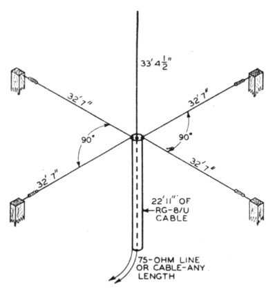
Fig. 1. Dimensions of the 7-Mc. ground-plane antenna. The radial wires are supported by any convenient means - W6TKX uses two poles, a telephone pole and a tree.
The four ground radials were made from 32-foot 7-inch lengths of No. 8 wire, all joined together at the junction of the two insulators. A piece of RG-8/U 52-ohm cable was used as a quarter-wave matching section at the bottom of the antenna, to match the antenna impedance to the 75-ohm transmission line that was used to the transmitter. The length of the quarter-wave section works out to be 22 feet, 11 inches, using a velocity factor of 0.66 for the line.(1) The shield braid of the cable was soldered to the junction of the four radial wires, and the inner conductor was soldered to the bottom of the vertical element. Either 75-ohm parallel line or 75-ohm coaxial (RG-11/U) can be used to the transmitter - the parallel line was used in this case.
The four radials were tied to various points that could be found - trees and poles - and they slope down slightly from the junction with the cable shield.
This antenna has been in use for over six months, and results have far exceeded the expectations. We can now call and raise the DX with just a short snappy call, instead of pounding brass for an hour to raise someone in the next state. Results now are better with only 300 watts input than they were with other antennas and a full kilowatt. Some of the DX stations worked on 40 meters from this West Coast QTH are ZL2MM, G3JA, HH2FE, CM2BC, PY1FW, VK3AMP, ZL3FP, PK6AQ, OZ7CC, CM2BC, ZL2GO, ZL4GM, XU1P. CO2SW and ZL2BH. During all of these contacts our signals were reported as S7 or better.
Notes
- The actual length of the quarter-wave section in use at W6TKX is 29 feet, 9 inches. This length was arrived at by experiment, and may possibly be accounted for by deviations from the correct length in the radiator and ground radials. The proper match can best be obtained by experiment and reference to the McWatters article in the May, 1947, issue of QST. - Ed.
Richard R. Schellenbach, W6TKX.