Triode mixer vs. pentode amplifier
Designing a weak-signal converter for 28 Mc.
The paramount requirement of a weak-signal receiver is the ability to distinguish signal over noise. Gain, while an essential factor, is relatively secondary to signal-to-noise ratio and bandwidth. It is also relatively easier to obtain. Assuming that means are taken to limit the receiver bandwidth to the narrowest usable value, gain may be added at the r.f., i.f. or audio ends of the receiver with equal results. I.f. gain is generally preferred for reasons of simplicity, stability and ease with which selectivity is obtained. R.f. gain or preselection is usually needed to overcome noisy mixer performance and improve image ratio; however, it involves ganging and stability problems.
It is not too widely appreciated that the signal-to-noise ratio of a receiver is largely established in the first stage. This follows since the inherent noise of the first stage is added to the signal and is amplified to the same extent by subsequent stages. It is thus necessary that the input stage of the weak-signal receiver possess the lowest possible tube and circuit noise. And, in order to present the largest possible signal to the input grid, the tuned input circuit must be of high Q and high impedance and be correctly coupled to the antenna. Broad-banding is out. The gain requirements of the input stage are not stringent so long as the signal is built up to a level where it completely masks the inherent noise of the following stage.
Tube noise
In designing a high-performance 10-meter converter it was first assumed that the most promising arrangement would consist of a stage or two of preselection using the "hot" 6AK5 followed by mixer and oscillator. Inquiry into the literature indicated that equivalent results could be obtained with far simpler means.
The noise energy developed in a tube is given by a figure called the "equivalent noise resistance," here abbreviated e.n.r. The e.n.r. is considered as that resistance which, if inserted in the grid circuit of the given tube, would produce as much noise energy as the tube does itself. For pentodes used as amplifiers:(1)
![]()
Where:
Ib = plate current in amperes,
Ig2 = screen current in amperes,
Gm = transconductance in mhos.
Solving for the 6AK5 as an amplifier:
This value is influenced by the random division of current that occurs between the screen and plate of a pentode. The e.n.r, of pentodes is usually 3 to 5 times greater than that of a triode giving equal amplification.
Triodes not only make quieter amplifiers but also quieter mixers than pentodes. The 6J6 with its high transconductance offered itself as a possibility.
The equivalent noise resistance of a triode as a plate-detection mixer is given as:(2),(3)
![]()
Where:
Go = transconductance in mhos at zero bias.
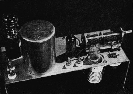
This top view of the converter chassis shows how the antenna coil can be moved into or out of the mixer grid coil to adjust the coupling to the optimum value. The shield can houses the i.f. output circuit.
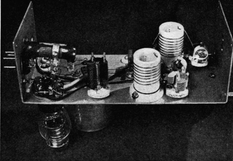
The oscillator circuit is in the foreground and the mixer input i circuit in the rear. The condenser between the oscillator coil and the VR-tube socket tunes the i.f. output circuit.
Then for a 6J6 triode section as a mixer,
![]()
Terman also shows that actual measured noise corresponds very closely to the values thus calculated. Clearly then, the use of pentode preselection would not essentially improve the signal-to-noise performance of such a mixer.(4)
This seemed to be a good point to put these conclusions to test. Accordingly the following circuit was projected and tried..
Circuit
As the schematic (Fig. 1) shows, the converter consists of a single 6J6, one triode section of which is used as a square-law (weak-signal) converter. The antenna coupling is variable to allow a proper impedance match. The coils are of high L and high Q. The cathode is grounded directly, thus improving stability and reducing interaction between mixer and oscillator. An i.f. of 6.8 Mc. was chosen since the performance of most commercial receivers still holds up in this region. The high-i.f. and high-Q circuits greatly reduce image interference.
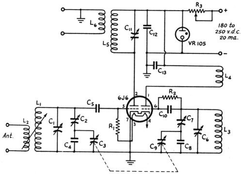
Fig. 1. Circuit diagram of the converter.
| C1 | 25 pF air padder. |
| C2,C7 | 4 to 30 pF ceramic trimmer. |
| C3,C9 | 50 pF per section variable. |
| C4 | 10 pF fixed ceramic. |
| C5,C10,C12,C13 | 120 pF fixed ceramic or mica. |
| C6 | 50 pF air padder. |
| C8 | 20 pF fixed ceramic. |
| C11 | 140 pF air padder. |
| R1 | 10 megohms, 1 watt (metalized). |
| R2 | 47,000 ohms, ½ watt. |
| R3 | 7000 ohms, 10 watts (Slideohm). |
| L1 | 28 to 30 Mc.: 8 turns No. 18 bare copper wire, length 1 inch on 1_1/8 inch diam. ceramic form. |
| L2 | 6 turns No. 22 e, length ¾ inch on ¾ inch polystyrene form. Variable insertion concentric with L1. Coupling adjusted for best signal-to-noise ratio. |
| L3 | 21.2 to 23.2 Mc.: 7 turns No. 18 bare copper, length 1 inch, on 1_1/8 inch diam. ceramic form. |
| L4 | 3 turns No. 22 e, close-wound on same form as L3, spaced 3/8 inch from cold end of L3. |
| L5 | 20 turns No. 22 e, length 1_½ inches on 1_1/8 inch diam. bakelite form. |
| L6 | 3 turns No. 22 e, close-wound on same form as L5, spaced ½ inch from cold end of L5. (For low-impedance coaxial line.) |
The oscillator section is entirely straightforward. The use of seriescapacitance bandspread may be questioned but the availability of inexpensive quality components makes this entirely practical.
After years of repruning of tapped coils, etc., it was a decided pleasure to be able to adjust bandspread and tracking at will by the turn of a screw. Injection for weak-signal reception was adequate with just the coupling introduced by socket and stray capacities. No "pulling" effects were observable.
The entire unit was built on an 8 × 4 × 3-inch "U"-shaped chassis which was bent up from a small stiff panel. The builder may incorporate such a dial and shielding as suit his taste.
No difficulty was experienced in putting the converter into operation except the usual one of finding the band. The mixer section operates at a plate current of 8 mA, which implies an average grid voltage of -0.75 volt. The mixer plate current without excitation is about 12 mA, well within the rating of the tube. It is not recommended or desirable that tube plate voltage of higher than 105 volts be used. The oscillator plate current is 3.5 mA. Mechanical and elec- ......
Almost any receiver may be used as an i.f. channel. It will help if there is ample gain, a low noise level and high selectivity. Particularly interesting for this purpose are the military receivers and fixed-tuned aircraft receivers.
Performance
By way of a preliminary listening check the converter was compared with a well-known communications receiver having two stages of tuned preselection. With the converter in and the receiver fixed at 6.8 Mc., about double the number of signals were readable on "ten" as when the receiver alone was tuned to "ten."
Subsequent precise measurements served to point up and define the following. A Hammarlund Comet Pro (of 1934 vintage) was used as the 6.8-Mc. i.f. channel. This receiver has no r.f. preamplification and a noisy mixer having an e.n.r. of about 50,000 ohms. With the converter connected and all voltages applied, the resultant increase in noise output was 0.25 dB. This is an insignificant figure and indicated that the signal-to-noise performance would be limited by the noise level of the Comet Pro.
Nonetheless, a 1 microvolt signal at 29 Mc.. modulated 30 per cent with 400 cycles, averaged 5.5 dB over noise. This figure was obtained without b.f.o. or crystal filter. This is a superior value but might further be improved by the use of :a quieter i.f. channel than the Comet Pro.5
Images are negligible. With the untuned antenna circuit shown, image rejection was better than 62 dB.
In conclusion, the converter described provides important signal-to-noise benefits with a notable economy of means. The improvement in reception of weak signals obtainable with it, over the "straight-through" operation of the finest commercial receivers, is about equivalent to raising the sending station's power by 4 times. This represents a gain in signal and not just noisy gain. There is no reason why the same circuit should not perform comparably well in the 50-Mc. band.
Notes
- W. A. Harris, R.C.A. Review, vol. 5, p. 514, April, 1941.
- F. E. Termen, Radio Engineers Handbook, p. 572.
- Tube data taken from curves supplied in R.C.A.'s HBd Handbook. Eb is 180 V in both cases. The 6AK5 as a plate-detection mixer has e.n.r. = 8346 ohms.
- The use of a triode preselector stage such as a 6J6 used as a cathode-coupled amplifier would appear to hold promise of further improvement of signal-to-noise ratio. It is proposed to treat this in a later article.
- Thanks to Robert Woolsey, W9RO, for his painstaking measurements of the converter's performance. I also wish to thank Earl Barrett, W9MGY, for many helpful suggestions during the course of this project.
Jerome Tannenbaum, W9RGS.