V.H.F. crystal oscillators
Regeneration in safe form, for improved output and keying.
A little regeneration, properly applied, will help to make sluggish crystals perform satisfactorily. It is particularly helpful in connection with crystal oscillators that operate at frequencies higher than about 10 Mc. Here the author shows how regeneration may be added to high-frequency crystal oscillators using both triode and pentode tubes, without adding to the circuit complication, and with complete safety as to crystal current and stability. The method has been used successfully with crystals operating as high as 68 Mc.
In the past there have been serious limitations to the use of crystals on frequencies higher than 10 Mc. If the crystals oscillated at all, they were usually very sluggish in their response, unstable and generally not to be depended upon. Recent improvements, however, in both harmonic and fundamental crystal units have helped considerably in overcoming these problems. The frequency range of the fundamental-type crystal has been extended to 20 Mc. The average crystal of this type has greater activity than the harmonic type, and gives better oscillator output. Third-harmonic type crystals are available for frequencies higher than 20 Mc.
In most cases, unfortunately, the amateur has had very little information concerning the design of reliable crystal oscillators for these frequencies. To drive amplifiers that operate in the v.h.f. bands, it has been considered necessary to use other amplifiers to multiply the lower crystal frequencies, making crystal control of v.h.f. transmitters both complicated and expensive. With crystals available and oscillators easily constructed for the higher frequencies, it is now quite common to see 30-Mc. transmitters with crystals on the same frequency, without intermediate multipliers. After all the years of development of frequency-stable oscillators, crystals are still the most practical means of obtaining an extremely stable signal.
The improvement described in this paper is accomplished by adding regeneration to the circuit, in such a manner that it can be adjusted to any desired value. One objection to crystal oscillators in the past has been the possibility of the crystal exhibiting multiple-frequency response or the oscillator self-oscillating. If the following construction notes are carefully followed, there will be no danger of self-oscillation; nor will there be any tendency toward multiple-frequency response, providing a crystal is used that has been properly finished.
Crystals above approximately 10 Mc. are more critical in their oscillator-circuit requirements. They cannot be used in just any type of circuit, but the new difficulties which arise do not represent any great problem when the facts are known. This paper will attempt to acquaint the reader with these facts. Tried circuits will be described which are recommended to the amateur. Various deviations in values and choice of component parts can be made as long as the basic ideas are followed.
Results of experiments
After carefully studying the tube manuals, the author selected several tubes which appeared to be the most readily available of the types that would serve for these high-frequency crystal oscillators. The tubes were tried in the circuits of Figs. 1 and 2.
These oscillator circuits are the conventional plate-tuned type, with the regeneration applied by means of coil L2. Table 1 tabulates the critical data of the experiments. The experiments were limited to voltages and currents that did not exceed the ratings of the tubes or endanger the crystal.
| Frequency in Megacycles | 28.921 | 28.921 | 28.921 | 28.921 | 28.921 | 28.921 |
|---|---|---|---|---|---|---|
| Circuit | Fig. 1 | Fig. 1 | Fig. 1 | Fig.2 | Fig. 2 | Fig. 2 |
| Tube | 6J4 | 6C4 | 6C4 | 6AG7 | 6V6GT | 6L6 |
| R.f. W output | 0.75 | 1.73 | 0.72 | 2.93 | 1.06 | 2.61 |
| D.c. W input (plate) | 2.3 | 4.55 | 2.37 | 8.62 | 2.65 | 5.25 |
| Ep d.c. V | 155 | 222 | 158 | 250 | 102 | 125 |
| Ip d.c. mA | 15 | 20.5 | 15 | 34.5 | 26 | 42 |
| ICrystal r.f. mA | 92 | 9.2 | 60 | 48 | 60 | 60 |
| Esg d.c. V | - | - | - | 140 | 102 | 125 |
| Isg d.v. mA | - | - | - | 11.5 | 2 | 3 |
| Self-oscillation starts at* ... | +10 pF | +10 pF | +10 pF | +10 pF | +10 pF | +10 pF |
*Method of indicating degree of applied regeneration - see text.
Circuit details
The purposes of the various component parts of Figs. 1 and 2 are outlined below. This will allow the reader to better understand the circuits and make deviations where necessary.
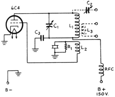
Fig. 1. Schematic diagram of the regenerative oscillator using a triode tube.
| C1 | 25 pF variable. |
| C2 | 75 pF variable. |
| C3 | 0.0047 µF mica. |
| R1 | 4700 Ω, ½ watt. |
| L1,L2,L3 | See Fig. 3 and text. |
| RFC | 2.5 mH r.f. choke. |
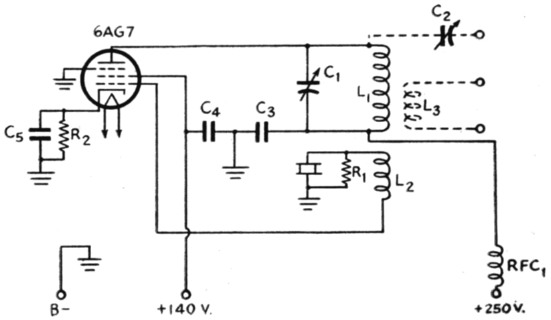
Fig. 2 - Circuit of the regenerative oscillator for pentode tubes. Values are similar to Fig. 1 except as indicated below.
C4,C5 0.0047 µF mica.
R1 3300 ohms, ½ watt.
R2 100 ohms, watt.
C1 - Plate tuning condenser: The capacity of this condenser should be kept low to maintain a high-impedance tuned circuit for better oscillator performance. A variable iron-core coil could be used, thereby eliminating this condenser if precautions outlined later in this article are followed.
C2 - Coupling condenser: The oscillator output to the load increases as the capacity of this condenser is increased to a certain optimum output point, which varies with different loads. After this correct value is found, a fixed condenser could be substituted. Capacity coupling direct to the plate side of the tuned circuit should be used whenever the load impedance approaches or exceeds the impedance of the oscillator output circuit. For very low impedances the inductance L3 could be used, but the capacity, in most cases, serves just as well.
C3, C4, C5 - Radio-frequency by-pass condensers: These condensers should be a noninductive type, mica preferred. Their reactance should be less than 10 ohms.
L1,L2 - Coils: For the particular oscillator used in our laboratory, the coils were constructed as shown in Fig. 3. These coils, with the associated parts as outlined in this paper, covr ered a frequency range of 23.5 to 33 Mc.
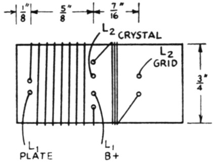
Fig. 3. Coil assembly used in the regenerative oscillators described.
L1 7 turns No. 18 enameled wire, space-wound.
L2 3 turns for triode oscillator, 2 turns for pentode, both of No. 24 d.c.c. wire, close-wound.
Coil form is Amphenol Type 24, ¾ inch diameter.
For other frequency ranges, change inductance of L1 and L2 but keep the turns ratio the same. The Q of the coils should be high. Use low-loss materials and keep the form clear of surrounding objects by a distance equivalent to at least three-quarters of its diameter. The number of turns and spacing of L2 with respect to L1 control the degree of regeneration. Extra space was provided on our coil form to allow this winding to be moved in its position from directly adjacent to Li to approximately 7/16 of an inch away. The adjustment of the winding is critical but is easily accomplished when the procedure outlined later is carefully followed.
L3 - Coupling coil: This coil is required only if inductive coupling to the oscillator is desired rather than the capacity coupling as outlined for C2. The number of turns and position with respect to L1 depend upon the impedance of the load and the amount of oscillator loading desired. It should be placed near the cold end of L1. Generally, unless the impedance of the load is quite low, capacity coupling is to be preferred.
Rl - Grid bias resistor: This resistor controls the amplitude of oscillations and affects plate current. Its value should be chosen for desired plate current and oscillator output. It should not be so low in value that it will hinder the operation of the crystal by shorting it out. This could be prevented by inserting an r.f. choke in series with it. An r.f. choke tried in our oscillators indicated that the value of resistance was not low enough to cause this difficulty. A lower-frequency crystal may require the choke because the radio-frequency resistance of the crystal increases as the frequency is lowered.
R2 - Cathode bias resistor: The purpose of this resistor is to limit the plate current drawn when the crystal is not oscillating. Its value must be chosen for the particular tube to keep its plate dissipation within its rating. Some tubes do not require this resistor if their plate dissipation is not exceeded with zero bias.
RFC - Radio-frequency plate choke: This choke is used to isolate radio frequency from the plate supply. Its value is generally not critical.
Oscillator Tube: A triode, tetrode, or pentode can be used. The screen voltage of the tetrode or pentode would be taken off the power supply either directly or through a resistor, depending on the particular requirements. Tubes designed for the high frequencies should be used.
Quartz-Crystal Unit: The crystal should have a temperature coefficient that will permit it to stay within the required frequency limits over the range of temperature at which it is expected to operate. The quartz plate should be etched the required amount to prevent future aging, and should have sufficient activity so that variation in temperature and circuit-component life will not reduce its value to such a level that the circuit will cease to function properly. If a crystal is allowed to arc, a foreign substance will form on the quartz plate causing its operation to become unstable.
During the tests the crystal showed indications of heating when it was subjected to a current greater than 80 milliamperes. It is therefore recommended that, for this frequency, this be the maximum current permitted. For a given size quartz plate the radio-frequency current through it increases and radio-frequency voltage across it decreases as the frequency is increased.
A 2-volt 60-ma. pilot light can be used in series with the crystal to indicate the current, but its resistance generally reduces the activity of the crystal to such a degree that the circuit will not deliver sufficient output. An r.f. milliammeter or thermogalvanometer is more satisfactory. It is essential that care be used in the choice and placement of parts to allow use of short lead length.
Adjustments
The grid current of an amplifier being driven by the crystal oscillator is a satisfactory means of checking radio-frequency output. If fixed bias is used on such an amplifier, it should be removed, since with a fixed bias there could be self-oscillation and the grid meter would not indicate until the bias voltage was exceeded.
The secret of applying the regeneration is to use only enough to permit the crystal to respond properly when the oscillator is turned on or keyed. The degree of regeneration' can be determined easily by putting a variable condenser in place of the crystal and increasing its capacity from its minimum setting until self-oscillation takes place as indicated by grid current in the succeeding stage. If the oscillator refuses to self-oscillate even with the crystal terminals shorted out, then the circuit is nonregenerative. The feed-back coil L2 may be found to be reversed or not coupled closely enough. The closer the coil is coupled, the smaller will be the capacity setting of the test condenser for the start of self-oscillation, and the greater the degree of regeneration.
The regeneration must not be such that the tube will self-oscillate because of the static capacity of the crystal, in case the crystal failed or the oscillator were detuned from the crystal frequency. The static capacity of the crystal is that which exists between the electrodes, holder contact plates, and pins. It can be easily measured by a capacity bridge or other testing device.
The test condenser which is substituted in place of the crystal should have the setting marked which is equal to the greatest expected static capacity of the crystals that are to be used. (The static capacity of the 28.921 Mc. crystal used in our tests was 17 pF) It should have short leads and be equipped with pins for plugging into the crystal socket. We used a variable Erie Ceramicon 7-45 pF. Type TS2A, mounted on a crystal holder.
After the test condenser has been marked for the static capacity of the crystal, the regeneration should then be adjusted to the proper degree. Apply only sufficient regeneration to make the crystal reliable in its response. Before making the final adjustment, the load (amplifier tube, etc.) must be connected to the oscillator. If, after the regeneration is adjusted, it is found necessary to change the coupling (C2 or in adjustment) to the load, it may be necessary to readjust the regeneration. This is necessary because, as the load on the oscillator is increased, the degree of regeneration must also be increased. The degree of regeneration also increases as C1 is decreased, therefore it should be adjusted with C1 at its lowest-capacity setting. In general, it is only necessary to have the circuit self-oscillate with a test capacity equivalent to the crystal static capacity plus 25 to 75 µµtd. An extra amount of regeneration beyond the point of reliable response does not materially affect the oscillator performance. Therefore, going beyond this point is neither necessary nor advisable.
Performance
The oscillator of Fig. 1 was tried with no regeneration applied (L2 removed and grid tied direct to crystal). Out of eighteen crystals tested, only three oscillated, and these three required the tuning to be backed off on the low-capacity side of resonance in order to make the crystals respond properly. When regeneration was applied, all the crystals responded 100 per cent and were as reliable as the lower-frequency crystals we have all used in the past.
The information in Table I allows us to reach the following conclusions:
- Of the tubes tried, the 6AG7 tube delivered the greatest power output for the lowest crystal current. Since the main limiting factor in the design of high-output crystal oscillators is the crystal current, the 6AG7 tube represents a step in the right direction.
- Of the three pentode tubes tried, the performance improved as their transconductance increased. This was not true with the two triodes; the 6J4 tube gave the poorest performance and it had the highest transconductance. However, the higher-transconductance tubes generally result in greater output for a given crystal current, providing other factors such as lead length, interelectrode capacities, etc. are not causing losses.
- Tests in Table 1 were all conducted with the same degree of regeneration applied as noted. Other tests proved that the same results would have prevailed if the regeneration was decreased to a lesser value, stopping of course where the crystal showed indications of improper response.
The circuit of Fig. 1, using a 6C4 tube and other coils, was tried with crystals as high in frequency as 68 Mc., with satisfactory results. It should thus be possible to have crystal-controlled transmitters without multipliers on frequencies as high as 60 to 100 Mc., opening possibilities for crystal control with less multiplier stages on frequencies higher than this.
From tests conducted with these and other oscillators, the author recommends that the reader use the grid current of the following amplifier to indicate the oscillator output. The plate current is not a satisfactory indication, since the oscillator's maximum output does not occur at minimum or maximum plate current.
The radio-frequency crystal-current peak was observed to be not at maximum output of the oscillator, but slightly on the low-capacity side of the adjustment of C1. Therefore it is advisable to tune the oscillator to its exact maximum output setting or slightly to the high-capacity side.
Notes
- A very satisfactory way of stating the degree of regeneration would be to state the amount of capacity (expressed in pF) in excess of that of the crystal static capacity necessary to start self-oscillation in the circuit. This is the method used in Table 1.
Gale B. Sells. W7AMQ.