Keying the tetrode amplifier
Reducing clicks by high-level keying.
When a gang of c.w. men work together during the day, and all live within a few miles of each other, the fellow who shows up with key clicks doesn't stand much of a chance. In this article W6BET describes a keying system that has done the trick for him and the other stations near-by.
Over the years it has become too common in some circles to tolerate moderate clicks, especially from near-by transmitters, on the basis that some clicks are "inevitable." That these clicks are not necessary is apparent to those who have eliminated them, and a circuit will be described that has worked well for a number of high-powered stations located within a radius of a few miles. If there is no frequency shift (chirp) with keying, and if the entire transmitter is free from regeneration and parasitic oscillations, it can be shown "on the 'scope" that the key clicks heard, even from near-by transmitters, are caused by too short a rise or decay time in the transmitter output. With the circuit to be described, the highest-speed hand keying can be perfectly clean-cut and devoid of clicks.
The principle involved is that of discouraging the keyed stage and what follows it from behaving like pulse-shaping or "sharpening" amplifiers. The common practice in transmitters keyed back near the oscillator is to fix-bias the following stages, to cut-off or beyond, so that they will draw no. plate, current under "key-up" conditions. Even if the keyed-stage output is devoid of clicks, each succeeding stage that is biased will tend to "sharpen" the character, and this introduces clicks. Running the stages with just enough fixed bias to keep the plates from burning up with no excitation will help some, but it's rough on the tubes and wasteful of power. Since each stage with cut-off fixed bias that follows the keyed stage adds clicks, one obvious thing to do is to move the key over as close as possible to the final, and then go to work on the click problem.
In a tetrode r.f. amplifier, the flow of plate current is dependent not only on control-grid bias and excitation but also the voltage applied to the screen grid. By keying the excitation and screen voltage simultaneously, it is possible to eliminate fixed bias on the tetrode amplifier stage. One system of this sort, using a separate small tube to control the screen voltage, has been described.(1)
Another system is shown in Fig. 1. V1 may be a small tetrode such as an 807, 6L6, 6F6 or what have you, depending upon the driving power required by the final amplifier and whether V1 is operated as an amplifier or frequency multiplier. V2 is a power-tetrode final amplifier. Although car pacitance coupling is shown between V1 and V2, link coupling may be used, of course. Driving power is fed to V1 continuously, and plate voltage remains on V2 at all times. Grid-leak bias is used for V1 and V2. The keying circuit controls the plate and screen voltage on V1 and the screen voltage on V2, which are all obtained from a common power supply of 500 volts or less. When the key is up there is no excitation to the final amplifier, and consequently no bias on the tube.
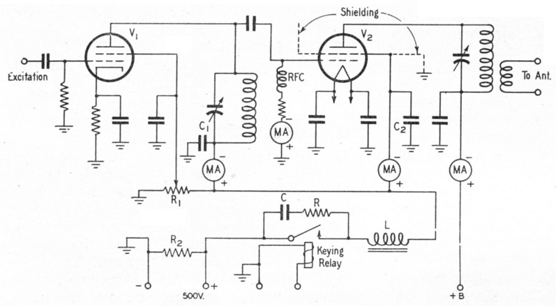
Fig. 1. Keying the driver stage, Vi, and the screen grid of the output amplifier, V2. eliminates the need for fixed bias on the output stage. The values of C, R and L (see text) determine the rise and decay time of the characters.
There is likewise no screen voltage on the final amplifier, and under these conditions the final amplifier will draw only a small amount of plate current. Under normal operation conditions, the key-up plate dissipation of the final-amplifier tube will be well under the maximum rated plate dissipation. Types 4-125A and 4-250A, for example, may be operated in this manner at their maximum rated plate voltage without exceeding the plate-dissipation rating, while the 4-65A may be operated at voltages up to 2000 volts.
Resistor R1 prevents the screen of V2 from charging up negatively by collecting stray electrons. A tap on R1 serves to supply screen voltage to V1 and, by adjusting this tap, the excitation to the final amplifier may be easily controlled. R2 is the normal power-supply bleeder.
A small relay insulated to withstand the screen potential (500 volts) is used to do the actual keying. Some relays not intended to be used for keying service exhibit a "bounce" characteristic 2 on the "make" that will make it more difficult to eliminate clicks by filtering. As a precaution, make sure the relay contacts do not chatter. Key clicks may be completely eliminated by the filter L-C-R in series with and across the keying relay. Choke L is best selected by trial. A satisfactory choke can be made by using any small power-supply choke, capable of handling the combined currents consumed by the buffer stage and final screen grid, and adjusting the air gap to give the proper inductance, as checked by observation of the keying characteristic on a scope or by listening for clean keying on the "make" side of the signal. R.f. by-pass capacitors C1 and C2 will have some effect on the required value of L as well as C. The values of R and C are likewise best selected by observation of the keying on an oscilloscope, but for many applications values of 500 ohms and 0.25 µF have been found quite satisfactory.
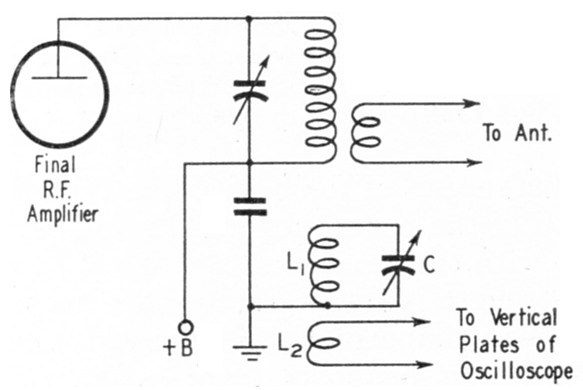
Fig. 2. Keying can be checked on a scope by coupling as shown above. The circuit L1C should resonate to the transmitter frequency, and a high C-to-L ratio is advisable to minimize uneven illumination of the pattern caused by harmonics in the output. The circuit is grounded to protect the scope and the operator.
Checking keying on a scope
If an oscilloscope is available, the proper method of adjusting the keying is to use very rapid dots and synchronize the oscilloscope sweep so that the pattern stays fixed in one place on the screen. Radio-frequency voltage is coupled from the final-amplifier plate tank to the vertical plates of the oscilloscope by means of a small tuned circuit of high C and a link, as shown in Fig. 2. Ground the link end of L1C during use. To obtain keying free of clicks it is absolutely essential that the rise and fall be gradual and not disturbed by any rapid changes in amplitude. The value of L controls the rate of rise at the start of the characters, and the values of R and C control the fall at the break. Fig. 3 shows the type of carrier envelope which should appear on the scope. Obtaining such a keying characteristic with the system described is simple and surefire.
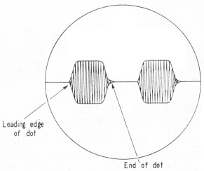
Fig. 3. A typical scope pattern showing two dots with the proper rise and decay times and shapes to avoid clicks.
Notes
- Smith, "A medium-power bandswitching transmitter," QST, Oct., 1946.
- Goodman, "Some thoughts on keying," QST, April, 1941.
Byron O. Ballou, " W6BET.