Voltage-multiplying circuits
A brief review of transformerless power systems.
Voltage-multiplying circuits, that is, power-supply circuits in which an a.c. voltage is changed to a higher d.c. voltage, have their widest application at the present time in television receiver circuits. However, frequent use is made of such circuits in ham gear where simplicity and light weight are prime considerations.
Voltage doublers
In Fig. 1, a condenser and rectifier in series are connected across a source of alternating voltage. When the polarity of the source is as shown in Fig. 1A, the rectifier will conduct and the condenser will become charged to the peak value of the a.c. voltage. When the source voltage reverses polarity, the rectifier will not conduct, but the polarities of the condenser charge and the source voltage will be such as to be additive. Therefore, when the source voltage reaches its peak value on this second half of the cycle, the voltage between points X and Y will be twice the peak value of the source voltage. This doubled voltage can be conducted through an additional rectifier, as shown in Fig. 2, to charge a second condenser to deliver twice the peak value of the source voltage to the load. Thus we have a circuit by which a voltage higher than the source voltage can be obtained without the use of a transformer. The circuit of Fig. 2 is called a voltage-doubler circuit. It should be noted that no current flows from the input circuit to the load during that portion of the cycle when the first condenser, C1, is being charged, because the polarity existing at that time is such as to make the rectifier, D2, nonconducting. Therefore, the circuit is a halfwave rectifier. However, the discharging of the condensers has a filtering action that smooths out the pulsations before reaching the load. The ripple voltage appearing across the load will depend on the capacitance of the condensers and the value of the load resistance, becoming smaller with an increase in each. For many applications, no further filtering is necessary. Capacitances of 40 tcfd. are commonly used throughout voltage-multiplying circuits. C1 should have a voltage rating at least equal to the peak value of the source voltage; C2 twice this value.
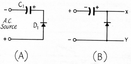
Fig. 1. In A the condenser is being charged. In B the voltage between points X and Y is essentially twice the peak value of the applied a.c. voltage.
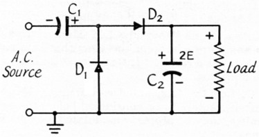
Fig. 2. A practical half-wave voltage-doubling circuit.
When more than a light load is placed across the output terminals of the circuit, of Fig. 2, the output voltage sags sadly. Regulation is a function of condenser capacitance and rectifier resistance, improving with an increase in capacitance and a decrease in resistance. An advantage of this circuit is that one side of the load circuit may be grounded directly.
Improvement in regulation and a reduction in the output ripple can be obtained by using a voltage-doubler circuit in which full-wave rectification takes place. Such a circuit is shown in Fig. 3. On one alternation (half cycle) one condenser is charged, while on the other alternation the other condenser is charged; hence full-wave rectification. The two charged condensers are in series across the load; hence voltage doubling. A disadvantage of this circuit in some applications is that neither side of the load circuit may be grounded. Both C1 and C2 should have a voltage rating at least equal to the peak value of the a.c. input voltage.
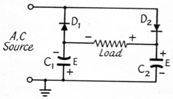
Fig. 3. A full-wave voltage-doubling circuit.
Voltage multipliers
The principle of voltage multiplication, that is, the charging up of a condenser through a rectifier during one alternation and the addition of the condenser charge to the line voltage on the other alternation can be extended beyond doubling to tripling, quadrupling and, indeed, to any number of stages. Fig. 4 shows a multiplier circuit having five sections. You will notice that the first two sections of this circuit are similar to the doubling circuit of Fig. 2. The condenser, C6, will be charged up to five times the peak voltage of the a.c. input voltage. To obtain the desired output voltage, it is necessary merely to employ the appropriate number of sections. E is the peak value of the applied input voltage. The condensers should have a voltage rating at least equal to this peak voltage times the number indicated in each section. The voltage regulation of such an arrangement gets worse as stages are added. For this reason, the condenser capacitances should be as large as practicable. At first glance, one might suspect that the inverse peak voltage across the rectifier increases with each stage, but such is not the case. Under no load, the peak inverse voltage across each rectifier is the same, i.e., twice the peak value of the a.c. input voltage. No matter how many stages, this type of circuit always gives half-wave rectification. As indicated, one side of the load circuit may be grounded.
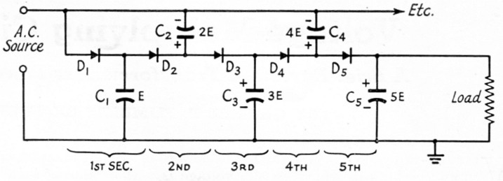
Fig. 4. Sections may be added to the voltage-doubling circuit to obtain any desired multiplication. The circuit shown at right will deliver an output voltage approximately equal to five times the peak value of the applied a.c. voltage at the input.
When tripling or quadrupling, better voltage regulation will be obtained with the circuits of Fig. 5. As with the full-wave doubler circuit, however, neither side of the load circuit can be grounded directly. In the tripler circuit of A, C1 and C3 should have a voltoge rating at least equal to the peak value of the a.c. source voltage, while the minimum voltage rating for Cry should be twice this value. In the quadrupler circuit of B, C1 and C4 should be rated for the peak of the source voltage and C2 and C3 for double this value.
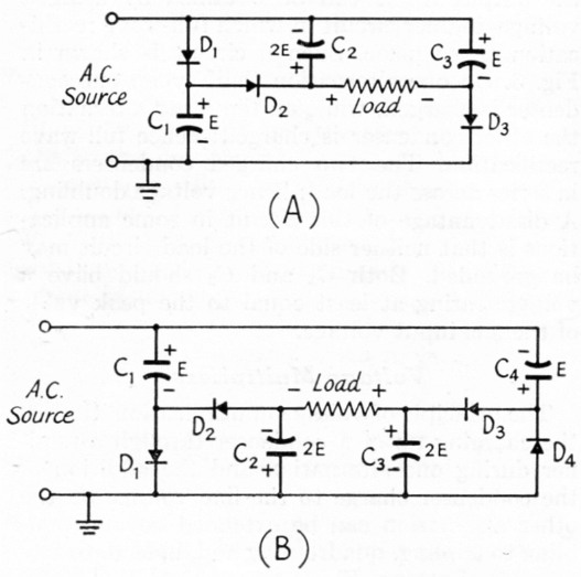
Fig. 5. (A) Voltage tripler. (B) Voltage quadrupler.
From an examination of these circuits, it will become evident that they are most practical for use with selenium or other types of rectifiers requiring no heated filament. The number of filament transformers will usually prohibit the use of vacuum-tube rectifiers. Since the capacitances required are large, such circuits are normally considered economically attractive when the output voltage is limited within the voltage ratings of electrolytic condensers.
Gabriel P Rumble, Ex W5BBB.